
Passive follow-up hydraulic robot rotary joint capable of continuously rotating

A hydraulic robot and rotary joint technology, applied in the field of robots, can solve the problems of robot safety to be improved, rotation angle limitation, hydraulic joint rotation angle limitation, etc., and achieve the effect of good passive follow-up characteristics and continuous rotation.

Active Publication Date: 2021-08-17
WUHAN UNIV OF SCI & TECH
View PDF9 Cites 0 Cited by
  • Summary
  • Abstract
  • Description
  • Claims
  • Application Information

AI Technical Summary

Problems solved by technology

However, there are fixed stops in its structure, and the angle of rotation of the hydraulic joint is limited to a certain extent.
[0005]Aiming at the problem that the above-mentioned hydraulic angle self-servo valve has rotation angle restrictions during the movement process, and the safety of hydraulic manipulator robots with large output torque needs to be improved

Method used


Image

  • Passive follow-up hydraulic robot rotary joint capable of continuously rotating
  • Passive follow-up hydraulic robot rotary joint capable of continuously rotating
  • Passive follow-up hydraulic robot rotary joint capable of continuously rotating

Examples


Embodiment Construction

[0054] The technical solutions of the present invention will be further specifically described below through the embodiments and in conjunction with the accompanying drawings.

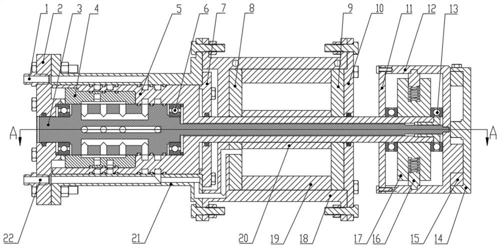
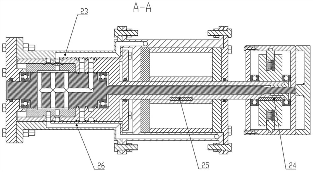
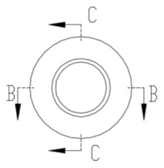
[0055] Such as Figure 1 to Figure 26 As shown, a rotary joint of a passive servo hydraulic robot capable of continuous rotation includes a valve core 3, a valve sleeve 4, a valve body 5, a hydraulic cylinder, a hydraulic motor and a variable stiffness mechanism, and the valve body 5 is an axial hollow part , which includes a valve body body 501 and a valve body output shaft 502. The valve body body 501 is installed in the hydraulic cylinder so that it can rotate freely. The valve core 3 and the valve body output shaft 502 extend out of the hydraulic cylinder and pass through the hydraulic motor. Connected with the flexible output mechanism, the valve core is coaxially installed in the valve body 5, one end of the valve core 3 protrudes from the tail of the hydraulic cylinder, and the other end protrud...


PUM


Abstract

The invention discloses a passive follow-up hydraulic robot rotary joint capable of continuously rotating. The passive follow-up hydraulic robot rotary joint comprises a valve element, a valve sleeve, a valve body, a hydraulic cylinder, a hydraulic motor and a variable stiffness mechanism. The valve element, the valve sleeve and the valve body are sequentially and coaxially mounted in the hydraulic cylinder, and output shafts of the valve element and the valve body extend out of the right end of the hydraulic cylinder, penetrate through the hydraulic motor and then are connected with a flexible output mechanism; the valve element, the valve sleeve, the valve body, the hydraulic cylinder, the hydraulic motor, a high-pressure oil path and a low-pressure oil path form a hydraulic corner self-servo mechanism; the variable stiffness mechanism comprises a separation disc, a sweeping arm disc and a load disc, the sweeping arm disc is mounted on the valve element, the separation disc is mounted on the output shaft of the valve body, power transmission is carried out between the sweeping arm disc and the separation disc through a first-stage flexible mechanism, and power transmission is carried out between the load disc and the sweeping arm disc through a second-stage flexible mechanism. When the joint encounters accidental collision, the joint can be quickly switched to a low-rigidity mode, the safety of the outside and the whole mechanism is guaranteed, and the joint can automatically recover to a high-rigidity mode after the collision is finished to continue normal operation.

Description

technical field [0001] The invention belongs to the field of robots, and relates to a joint technology of a hydraulic robot, in particular to a rotary joint of a passive follow-up hydraulic robot capable of continuous rotation. Background technique [0002] The hydraulic angle servo joint technology combines hydraulic pressure and motor technology. Using their respective advantages, the small torque of the motor directly drives the valve core to open the valve port, and the high-pressure oil pushes the vane to drive the valve body to rotate, thereby obtaining a large output torque. The hydraulic angle self-servo valve is the core component of the hydraulic control system. It has the characteristics of high precision and fast response. It is widely used in high-precision mechatronics systems, aerospace airborne drive systems, and large-scale test equipment. Therefore, Get the attention of scientific and technological personnel at home and abroad. [0003] This patent is base...

Claims


Application Information

Patent Timeline
Patent Type & Authority Applications(China)
IPC IPC(8): B25J17/02B25J9/14
CPCB25J17/0258B25J9/146
Inventor 赵慧罗建雄蒋林刘方松周玲王诗虎朱发强
Owner WUHAN UNIV OF SCI & TECH
Learn More