
A Composite Cooling Structure of Turbine Guide Vane End Wall

A turbine guide vane and composite cooling technology, applied in the field of blade cooling, can solve the problems of external film cooling performance degradation, internal impingement cooling performance degradation, impact cooling heat transfer level decline, etc., to save cooling air consumption and improve comprehensive cooling Performance, the effect of improving the impact heat transfer level

Active Publication Date: 2022-02-01
XI AN JIAOTONG UNIV
View PDF6 Cites 0 Cited by
  • Summary
  • Abstract
  • Description
  • Claims
  • Application Information

AI Technical Summary

Problems solved by technology

However, in these common layout methods, the outlet pressure of each exhaust membrane hole is quite different. If it is used together with internal impingement cooling, it will lead to very uneven output of cold air, which will degrade the performance of internal impingement cooling. At the same time, the external air The performance of film cooling also degrades
In terms of impingement cooling inside the end wall, the biggest defect of traditional impingement cooling is that the cross flow formed by the impingement jet will deflect the impingement jet downstream of the cross flow, which will reduce the heat transfer level of the impingement cooling. Therefore, the development of an impingement cooling structure that can effectively prevent the cross flow from affecting Improving the performance of impingement cooling is critical
The existing one is to extend the impingement hole into the impingement cavity on the simple flat model to prevent the deflection of the cross flow, but the extended impingement cooling structure and the film cooling layout are co-designed and applied to the high-efficiency composite cooling of the turbine guide vane end wall The cooling structure has not been reported yet

Method used


Image

  • A Composite Cooling Structure of Turbine Guide Vane End Wall
  • A Composite Cooling Structure of Turbine Guide Vane End Wall
  • A Composite Cooling Structure of Turbine Guide Vane End Wall

Examples


Embodiment Construction

[0038] The following will clearly and completely describe the technical solutions in the embodiments of the present invention with reference to the accompanying drawings in the embodiments of the present invention. Obviously, the described embodiments are some of the embodiments of the present invention, but not all of them. Based on the embodiments of the present invention, all other embodiments obtained by persons of ordinary skill in the art without making creative efforts belong to the protection scope of the present invention.

[0039] In describing the present invention, it should be understood that the terms "center", "longitudinal", "transverse", "upper", "lower", "front", "rear", "left", "right", " The orientation or positional relationship indicated by "vertical", "horizontal", "top", "bottom", "inner", "outer", "side", "end", "side" etc. is based on the Orientation or positional relationship is only for the convenience of describing the present invention and simplif...


PUM


Abstract

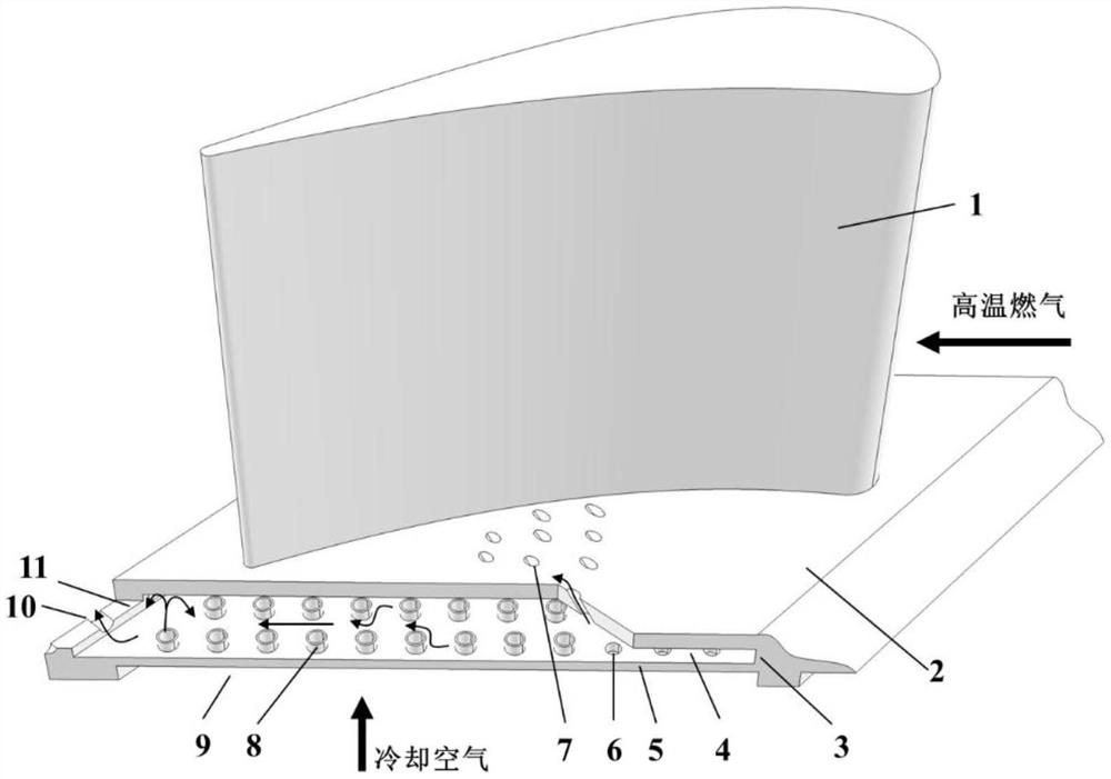
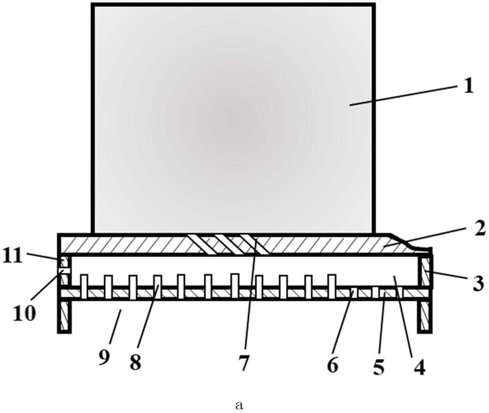
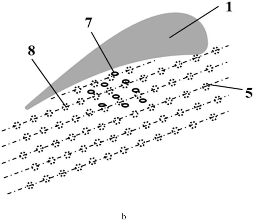
The invention discloses a composite cooling structure for the end wall of a turbine guide vane. The first air film holes include multiple rows and are arranged at intervals on the end wall of the guide vane. The wall is connected to the impact plate, and there are multiple rows of impact holes arranged on the impact plate. There is a fork row between the impact holes and the first air film hole, and a second air film hole is arranged on the side wall of the impact chamber trailing edge. The cooling air is impacted The hole impinges on the inner side of the end wall of the guide vane to form an impact cross flow, and the impact cross flow passes through the first film hole and the second film hole respectively to realize film cooling on the outside of the end wall and secondary cooling on the downstream end wall. The present invention takes into account the performance improvement of the internal impingement cooling of the end wall and the external air film cooling, and fully exerts the synergistic effect of the two, effectively improving the comprehensive cooling performance of the end wall, and at the same time utilizing the cold air to secondary cool the end wall of the downstream moving blade Effect, reducing the amount of cold air used on the end wall, which is conducive to improving the overall performance of the aero-engine.

Description

technical field [0001] The invention belongs to the technical field of blade cooling, and in particular relates to a composite cooling structure of a turbine guide vane end wall. Background technique [0002] As the turbine inlet temperature of advanced aero-engines continues to increase and the outlet temperature of the high-efficiency and low-emission combustion chamber becomes more flat along the blade span, the high-pressure turbine end wall, especially the first-stage guide vane end wall, is facing increasingly severe high-temperature ablation problems. Therefore, an efficient cooling structure must be designed for the end wall for thermal protection. However, in the cascade channel, the flow structure near the end wall is very complex, and there are complex and diverse strong three-dimensional secondary flows, which bring huge technical challenges to the cooling structure design of the end wall. In the early days, end wall cooling technology generally used a single ex...

Claims


Application Information

Patent Timeline
Patent Type & Authority Patents(China)
IPC IPC(8): F01D9/02F01D25/12
CPCF01D9/02F01D25/12F05D2260/201F05D2260/202
Inventor 杨星丰镇平
Owner XI AN JIAOTONG UNIV
Learn More