Lithium battery diaphragm conductivity testing device

A lithium battery separator and testing device technology, which is applied in the measurement device, the measurement device casing, and the measurement resistance/reactance/impedance, etc., can solve the problems of result error, high testing cost, and high cost, and achieves increased diversification, clever design, time saving effect

Active Publication Date: 2021-08-17
JIANGXI RUIDA NEW ENERGY TECH CO LTD
View PDF10 Cites 0 Cited by
  • Summary
  • Abstract
  • Description
  • Claims
  • Application Information

AI Technical Summary

Problems solved by technology

When directly testing the conductivity of the diaphragm, there is a large error between the obtained result and the real value. Because the diaphragm itself is relatively thin, it is difficult to accurately control the distance between the electrodes. In addition, the roughness of the contact surface between the electrode plate and the diaphragm also significantly affects the test. Accuracy of results
Therefore, to strictly control the distance between the electrodes and the roughness of the contact surface between the electrodes and the diaphragm, many equipments are required, many testing procedures are required, and the testing cost is high.
At present, most of the general-purpose surface resistance testing equipment is used to evaluate the lithium battery separator. Due to the particularity of the material of the separator, the general-purpose surface resistance testing equipment is more complicated when testing the separator, the operation is cumbersome, the cost is high, and the test method is single. The error is large, and some even have potential safety hazards

Method used


Image

  • Lithium battery diaphragm conductivity testing device
  • Lithium battery diaphragm conductivity testing device
  • Lithium battery diaphragm conductivity testing device

Examples


Embodiment Construction

[0034] The following will clearly and completely describe the technical solutions in the embodiments of the present invention with reference to the drawings in the embodiments of the present invention.

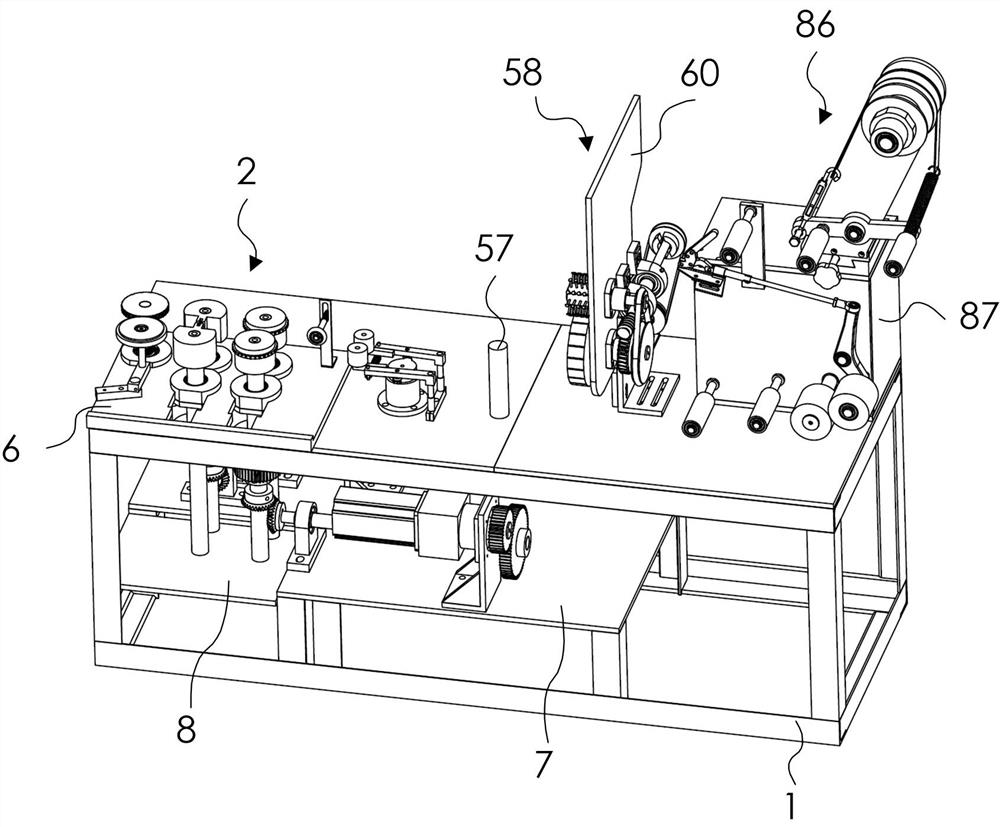
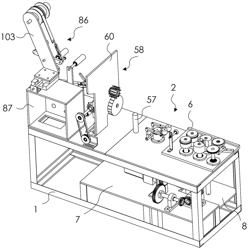
[0035] like Figures 1 to 14 As shown, the conductivity testing device of this lithium battery diaphragm of the present invention includes a first test mechanism 2, a second test mechanism 58 and a test platform 1, and the first test mechanism 2 and the second test mechanism 58 are installed on the test platform 1 superior.

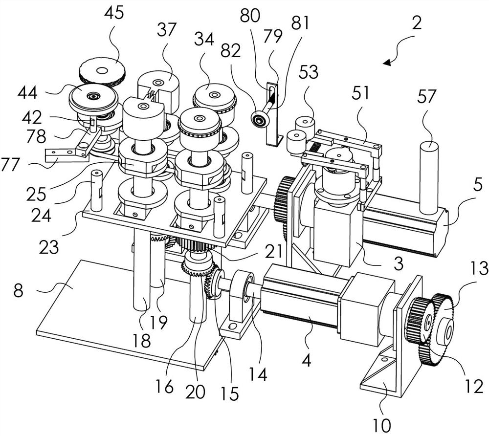
[0036] The first testing mechanism 2 includes a first motor 3 , a second motor 4 , a third motor 5 , a first support plate 6 , a second support plate 7 and a third support plate 8 . The first support plate 6 is installed on the test platform 1, the second support plate 7 and the third support plate 8 are installed in the middle of the test platform 1, the second support plate 7 has a second mount 10 and a third mount 11, The second motor 4 is mounted on...


PUM


Abstract

The invention discloses a lithium battery diaphragm conductivity testing device which comprises a first testing mechanism, a second testing mechanism, a third testing mechanism and a testing platform, and the first testing mechanism, the second testing mechanism and the third testing mechanism are installed on the testing platform. The lithium battery diaphragm conductivity testing device is compact in structure and ingenious in design, conductivity testing can be conducted on the folded diaphragm through the first testing mechanism, conductivity testing can be conducted on the surrounding diaphragm through the second testing mechanism, and the third testing mechanism can test the diaphragm under stretching rotation and under the condition that the stretching force is changed. Diversification of tested diaphragm conductivity information is increased, accuracy of diaphragm conductivity test data is achieved, diaphragm test efficiency can be improved, and time is saved.

Description

technical field [0001] The invention relates to the technical field of testing lithium battery diaphragms, in particular to a conductivity testing device for lithium battery diaphragms. Background technique [0002] The separator is used as an insulating material to isolate the positive and negative electrodes in the lithium battery without short-circuiting the battery. At the same time, because the separator has a certain pore structure and allows lithium ions to pass through freely, the performance of the separator directly affects the performance of the battery, especially It plays an extremely important role in the safe use of lithium batteries. In the manufacturing process of lithium-ion batteries, it is necessary to conduct a short-circuit test on the winding cell. If the breakdown voltage of the diaphragm is too small, the diaphragm will be broken down during the test, and the winding core will be scrapped, which will reduce the battery yield and cost waste. When the...

Claims


Application Information

Patent Timeline
Patent Type & Authority Applications(China)
IPC IPC(8): G01R27/02G01R1/04
CPCG01R1/04G01R27/02
Inventor 韩旗英
Owner JIANGXI RUIDA NEW ENERGY TECH CO LTD
Why Eureka
Try Eureka