Exercise recovery device for orthopedics department

A No. 1 technology for orthopedics and traumatology, applied in the field of exercise recovery devices for orthopedics and traumatology, which can solve the problems of inconvenient portability, single function, and inconvenient use

Inactive Publication Date: 2021-08-20
KAIFENG CENT HOSPITAL
View PDF2 Cites 3 Cited by
  • Summary
  • Abstract
  • Description
  • Claims
  • Application Information

AI Technical Summary

Problems solved by technology

[0007] The purpose of the present invention is to solve the problem that most of the recovery aids in the orthopedics department in the prior art are relatively simple and have a single function, an

Method used


Image

  • Exercise recovery device for orthopedics department
  • Exercise recovery device for orthopedics department
  • Exercise recovery device for orthopedics department

Examples


Embodiment 1

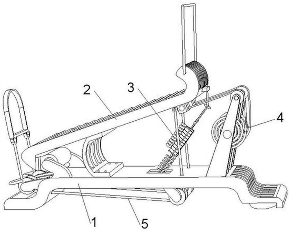
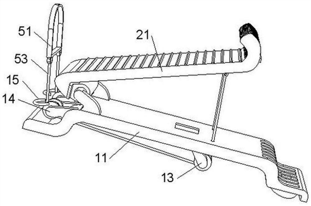
[0048] Such as figure 1 , Figure 6 , Figure 7 and Figure 8 As shown, the present invention provides a technical solution: an exercise recovery device for orthopedics, including a bottom frame mechanism 1, the bottom frame mechanism 1 includes a bottom support plate 11, and the bottom support plate 11 is far away from the second guide pulley block 14. A rubber fixed suction cup 12 is fixedly installed on the lower side of one end, and an opening is provided through the corresponding bottom support plate 11 above the rubber fixed suction cup 12. One end of the upper side of the bottom support plate 11 is fixedly connected with a rotating connecting frame 16, and the rotating connecting frame 16 rotates. Connected with the transmission contact plate mechanism 2, a No. 1 guide pulley block 13 is fixedly installed on the lower side of the bottom frame body mechanism 1, and the side of the rotating connecting frame 16 away from the No. 1 guide pulley block 13 is fixedly install...

Embodiment 2

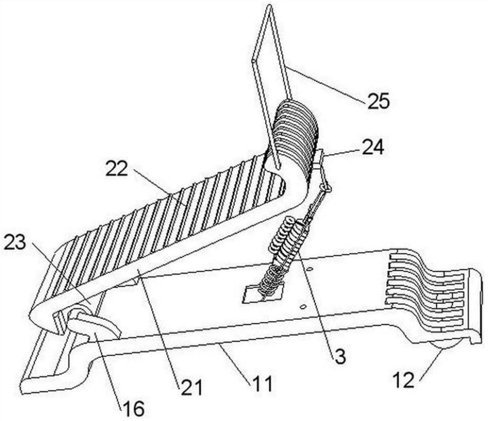
[0051] Such as figure 1 , figure 2 , image 3 , Figure 4 and Figure 8 As shown, the transmission touch plate mechanism 2 includes an S-shaped pedal 21, and a plurality of anti-skid lines 22 are embedded in the upper side of the S-shaped pedal 21. One end of the anti-skid lines 22 is provided with a rotating edge 23, and the rotating edge 23 is connected to the rotating connecting frame 16. Rotating connection between them, the S-shaped pedal 21 is fixedly welded with a connecting block 24 on the outside of one end away from the rotating side 23, and the two ends of one side of the S-shaped pedal 21 where the connecting block 24 is located are respectively fixed to the two ends of the pull sleeve 25. Connection, the lower side of the S-shaped pedal 21 is in contact with a spring plate 26, and the side of the spring plate 26 away from the S-shaped pedal 21 is connected to the bottom support plate 11 by rivets.

[0052] In this embodiment, through the design of the rotatio...

Embodiment 3

[0054] Such as figure 1 , Figure 9 and Figure 10 As shown, the stepping weight mechanism 3 includes a limit ring 31, and limit slide rods 32 are fixed on the opposite ends of the limit ring 31. Above, a telescopic suspension rope 34 is fixed in the middle of the sliding suspension rod 33, the telescopic suspension rope 34 is set through the limit ring 31, and the end of the telescopic suspension rope 34 away from the sliding suspension rod 33 is fixedly connected with the connecting block 24, the sliding suspension The two ends of the side of the bar 33 away from the limit ring 31 are vertically fixedly welded with a double-track frame bar 35, and the end of the double-rail frame bar 35 away from the sliding suspender 33 is vertically fixed on the load-carrying frame plate 36, and the load-carrying frame plate 36 is set Between the two limit slide bars 32, a sliding link 37 is fixedly welded on the side surface of the load-carrying frame plate 36 away from the double-rail ...


PUM


Abstract

The invention provides an exercise recovery device for orthopedics department, and relates to the technical field of rehabilitation instruments. The exercise recovery device comprises a bottom frame body mechanism, the bottom frame body mechanism comprises a bottom supporting plate, one end of the upper side face of the bottom supporting plate is fixedly connected with a rotating connecting frame, and the rotating connecting frame is rotationally connected with a transmission touch plate mechanism; a first guide pulley block is fixedly installed on the lower side face of the bottom frame body mechanism, and a second guide pulley block is fixedly installed at the position, corresponding to the upper side face of the bottom supporting plate, of the side, away from the first guide pulley block, of the rotating connecting frame. Meanwhile, push-pull training can be carried out on the arms of a patient, the practicability and the application range of the device in use are greatly improved. The device is novel in structure, small and exquisite and convenient to carry, the device can be used only by adsorbing and fixing one end of the device to the ground through a rubber fixing suction cup in use, carrying and mounting are convenient, and the use convenience of the device is greatly improved.

Description

technical field [0001] The invention relates to the technical field of rehabilitation equipment, in particular to an exercise recovery device for orthopedics. Background technique [0002] TCM orthopedics is a science that studies the prevention and treatment of injuries and diseases of human skin, muscles, bones, qi and blood, viscera and meridians. TCM orthopedics has a long history and was created and developed during the long-term struggle of people of all nationalities in our country against traumatic diseases. It has formed a rich theoretical system and has become an independent discipline. It is an important part of Chinese medicine and has contributed to the prosperity of the Chinese nation and the development of medicine. [0003] However, in the prior art, most of the existing orthopedic recovery aids are relatively simple and have a single function, and can only restore fixed parts, which is not only inconvenient to carry, but also has a large workload when arrang...

Claims


Application Information

Patent Timeline
IPC IPC(8): A63B23/04A63B21/02A63B21/08A63B23/12A63B23/14
CPCA63B21/026A63B21/08A63B23/04A63B23/12A63B23/14
Inventor 王楠
Owner KAIFENG CENT HOSPITAL
Why Eureka
Try Eureka