Copper foil cooling water plate structure convenient for cleaning blockage

A technology for cooling water plates and cooling plates, which is applied in the direction of cleaning heat transfer devices, fixed plate conduit components, heat exchange equipment, etc., and can solve problems such as complicated cleaning steps

Pending Publication Date: 2021-08-20
陕西汉和新材料科技有限公司
View PDF0 Cites 0 Cited by
  • Summary
  • Abstract
  • Description
  • Claims
  • Application Information

AI Technical Summary

Problems solved by technology

[0002] When the conventional cooling water plate needs to be cleaned, because it is mainly assembled together by bolts, it is necessary to unscrew many bolts when disassembling, then disassemble and clean it, and then assemble it after cleaning, and then screw Tighten and fix together, resulting in the problem of complicated cleaning steps, so a solution that can alleviate the above problems is urgently needed

Method used


Image

  • Copper foil cooling water plate structure convenient for cleaning blockage
  • Copper foil cooling water plate structure convenient for cleaning blockage
  • Copper foil cooling water plate structure convenient for cleaning blockage

Examples


Embodiment 1

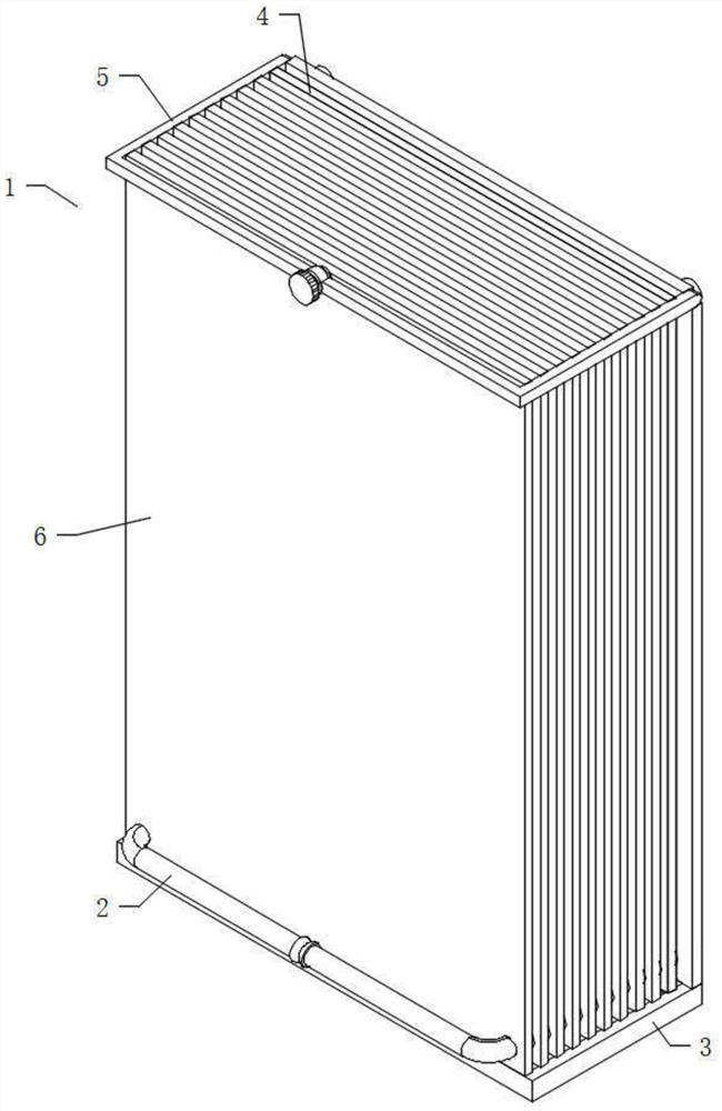
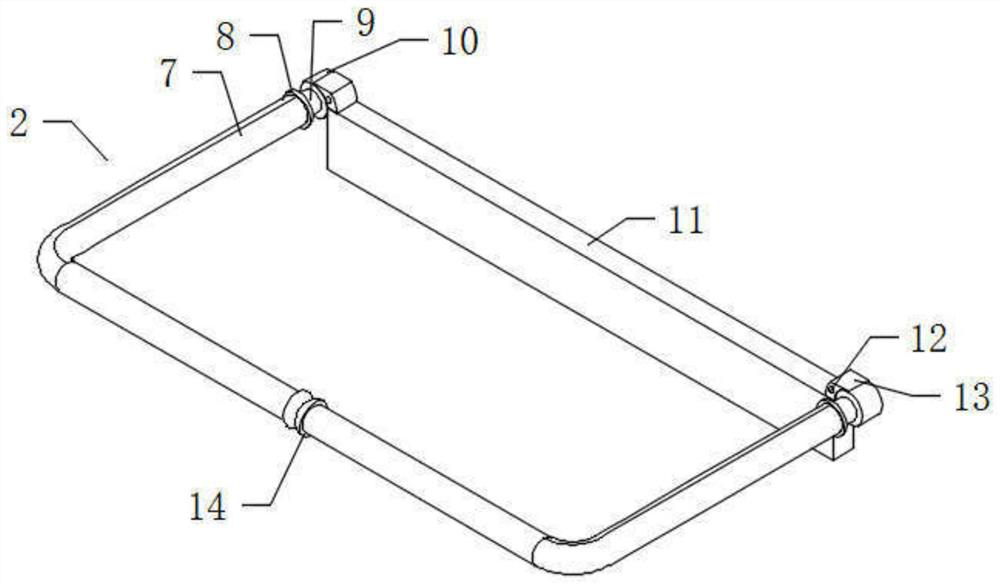
[0026] see Figure 1-4, an embodiment provided by the present invention: a cooling water plate structure for convenient cleaning of clogged copper foil, including a cooling water plate cleaning mechanism 1, a cooling water plate cleaning mechanism 1 including a guiding body 2, a main frame 3, a cooling Plate installation frame 4, restraint frame 5 and flip cover 6, guide body 2 and main frame 3 are rotated and installed together, cooling plate installation frame 4 and guide body 2 are slidably installed together, and the rear end of restraint frame 5 is rotated and installed with main frame 3 Together, the binding frame 5 is socketed and installed on the outer ends of a cooling plate installation frame 4 and the flip cover 6, and the flip cover 6 and the guide body 2 are slidably installed together, and the cooling plate installation frame 4, the flip cover 6 are in sliding contact with the main frame 3; The main body 2 includes an L-shaped guide rod 7, a retaining ring 8, a f...

Embodiment 2

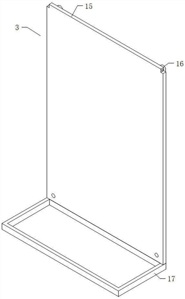
[0032] see Figure 5 , an embodiment provided by the present invention: the restraint frame 5 includes a second frame body 22, a second rotating shaft 23, a nut 24 and a bolt 25, the second frame body 22 and the nut 24 are fixedly connected as one, and the second rotating shaft 23 is provided with a Yes, the second rotating shaft 23 is fixedly connected with the rear part of the second frame body 22 , the second rotating shaft 23 is rotatably inserted into the upper side end of the back plate 15 , the bolt 25 passes through the nut 24 , and the bolt 25 and the nut 24 are screwed together , the rear end of the bolt 25 is movable and squeezed on the upper front end of the flip cover 6; when the restraint frame 5 needs to be opened, the bolt 25 is loosened forward first, and then the second frame body 22 is turned upwards, and the bolt 25 is tightened way, to achieve the purpose of fixedly installing the tethering frame 5 and the flip cover 6 together.

[0033] The restraint fra...

Embodiment 3

[0035] see Figure 6 , an embodiment provided by the present invention: the flip cover 6 includes a cover plate 27, a binding ring 29 and a second sliding hole 31, the binding ring 29 is fixedly connected to the upper front end of the cover plate 27, and the binding ring 29 is movably socketed on the bolt 25 At the outer end of the rear part, the second sliding hole 31 is symmetrically opened on the lower end of the cover plate 27, and the second sliding hole 31 is slidingly sleeved and installed on the outer wall of the L-shaped guide rod 7; 5 is firmly tied to the front end of the cover plate 27, so as to achieve the purpose of a stable locking state.

[0036] The flip cover 6 also includes a second spacer block 28 , which is symmetrically and fixedly connected to the upper rear end of the cover plate 27 ; the distance between the cover plate 27 and the first frame body 18 is stabilized by using the second spacer block 28 .

[0037] The flip cover 6 also includes a second s...


PUM


Abstract

The invention discloses a copper foil cooling water plate structure convenient for cleaning blockage, the copper foil cooling water plate structure comprises a cooling water plate convenient cleaning mechanism, the cooling water plate convenient cleaning mechanism comprises a guide main body, a main frame, a cooling plate mounting frame, a binding frame and a flip cover, and the guide main body and the main frame are rotatably mounted together. The cooling plate mounting frame and the guide main body are slidably mounted together, the rear end of the binding frame and the main frame are rotatably mounted together, the binding frame is mounted at the outer ends of the cooling plate mounting frame and the flip cover in a sleeving manner, the flip cover and the guide main body are slidably mounted together, and the cooling plate mounting frame and the flip cover are in sliding contact with the main frame. The guide main body comprises a pair of L-shaped guiding rods, a baffle ring, a first rotating shaft, a limiting block, a spherical convex block, a first baffle block and a second baffle block. The invention relates to the technical field of cooling water plate equipment, the cooling water plate can be conveniently unfolded and closed, so that the overall cleaning work is facilitated, and the use requirements are better met.

Description

technical field [0001] The invention relates to the technical field of cooling water plate equipment, in particular to a cooling water plate structure for conveniently cleaning clogged copper foil. Background technique [0002] When the conventional cooling water plate needs to be cleaned, because it is mainly assembled together by bolts, it is necessary to unscrew many bolts when disassembling, then disassemble and clean it, and then assemble it after cleaning, and then screw Tighten and fix together, thereby causing the problem that the whole cleaning process is complicated, so a kind of scheme that can alleviate the above-mentioned problem is urgently needed. Contents of the invention [0003] The object of the present invention is to provide a cooling water plate structure for copper foil that is convenient for cleaning blockages, so as to solve the problems raised in the above-mentioned background technology. [0004] In order to achieve the above object, the present...

Claims


Application Information

Patent Timeline
Patent Type & Authority Applications(China)
IPC IPC(8): F28D9/00F28F9/007F28F9/10F28G15/00
CPCF28D9/00F28F9/007F28F9/10F28G15/00
Inventor 赵文静王菲张荣冯芹芹唐宏洁尹朋朋
Owner 陕西汉和新材料科技有限公司
Why Eureka
Try Eureka