Shield tunnel excavation model test box

A technology of model testing, shield tunneling, applied in the direction of applying stable tension/compression to test the strength of materials, measuring devices, instruments, etc.

Active Publication Date: 2021-08-20
CHINA RAILWAY FIRST SURVEY & DESIGN INST GRP
View PDF11 Cites 3 Cited by
  • Summary
  • Abstract
  • Description
  • Claims
  • Application Information

AI Technical Summary

Problems solved by technology

[0003] However, there is currently no test chamber that can better simulate the mechanical impact of shield tunneling on existing structures, so this test chamber will be

Method used


Image

  • Shield tunnel excavation model test box
  • Shield tunnel excavation model test box
  • Shield tunnel excavation model test box

Examples


Embodiment Construction

[0024] In order to understand the above-mentioned purpose, features and advantages of the present invention more clearly, the present invention will be further described in detail below in conjunction with the accompanying drawings and specific embodiments. It should be noted that, in the case of no conflict, the embodiments of the present application and the features in the embodiments can be combined with each other.

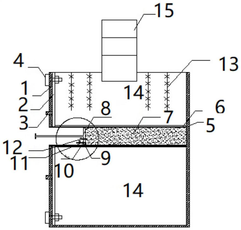
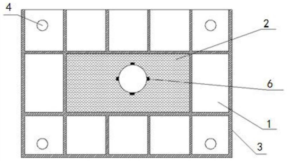
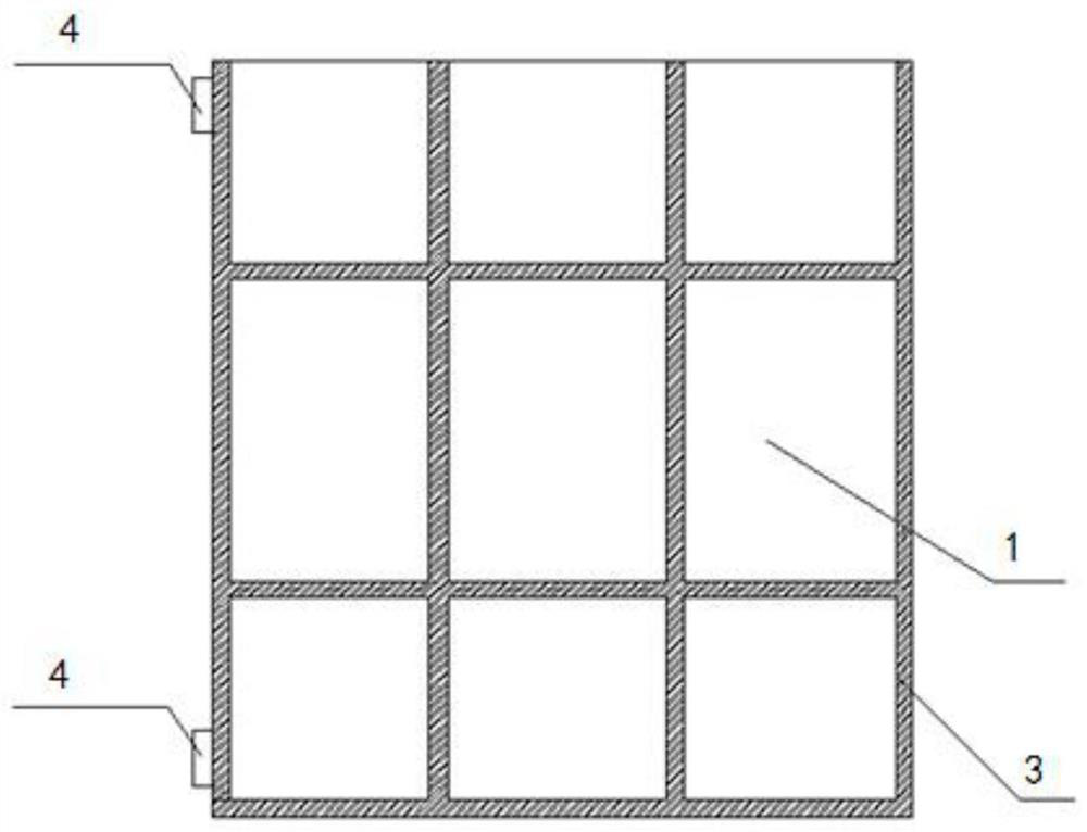
[0025] The shield tunnel excavation model test box according to the embodiment of the present invention is a test box for simulating the impact of the shield excavation process on the existing structure, which simulates the shield tunneling process by simulating segments, hydraulic oil, and pistons. Such as Figure 1 to Figure 4 As shown, the test box of the present invention includes a box body, tempered glass 2, stiffening rib 3, fixing bolt 4, simulated segment 5, fiber grating 6, hydraulic oil 7, piston 8, plastic sealing rubber plug 9, oil valve 10, Flow...


PUM


Abstract

The invention relates to a shield tunnel excavation model test box. A box body front part, a box body rear part, two side walls of the box body and the bottom of the box body are steel plates; tempered glass layers are arranged in the inner sides of the front portion of the box body, and tempered glass of the tempered glass layers is fixed to a steel plate on the front portion of the box body through fixing bolts; reinforcing ribs are arranged in the outer sides of the steel plates, and a simulation duct piece is arranged in the box body in a penetrating manner; a fiber bragg grating is arranged in the outer side of the simulation segment; a piston is arranged in the simulation duct piece, the piston is connected with loading equipment through a piston rod, a hydraulic cavity for containing the hydraulic oil is formed between the piston and the sealing end of the simulation duct piece, the inner space of the box body on the outer side of the simulation duct piece is filled with the soil body, and the existing structure is arranged at the top of the box body; and a multi-point displacement meter is buried in a soil body in the box body, and vertical differential settlement of the soil body is monitored through the multi-point displacement meter.

Description

technical field [0001] The invention relates to the technical field of tunnel excavation, and more specifically, the invention relates to a shield tunnel excavation model test box. Background technique [0002] At present, in the context of urban traffic congestion and increasingly tight land, city planners are tending to alleviate this contradiction by building subway projects. The construction site of the subway is often located on a busy road in the city, so the construction of the subway using the shield method is often the choice of the engineer. However, during the construction of the subway, it often affects the surrounding existing structures. During the construction process, many reasons lead to the uneven settlement of the surrounding soil, which destroys the original stress field and leads to the destruction of the existing structures. Therefore, when designing, it is necessary to simulate the mechanical influence during the construction process through model te...

Claims


Application Information

Patent Timeline
IPC IPC(8): G01N3/12G01N3/06
CPCG01N3/12G01N3/06G01N3/068G01N3/064G01N2203/0019G01N2203/0048G01N2203/0611G01N2203/0641G01N2203/0676G01N2203/0682
Inventor 李国良黄双林丁正全杜孔泽王飞刘小刚李骏王煦霖刘鹏赵晓勇刘建红张景尹陇娟
Owner CHINA RAILWAY FIRST SURVEY & DESIGN INST GRP
Why Eureka
Try Eureka