Eureka AIR delivers breakthrough ideas for toughest innovation challenges, trusted by R&D personnel around the world.

Load driving circuit and driving method

A technology of load driving circuit and load voltage, which is applied in the electronic field, can solve the problems of switching color temperature flickering, low overall efficiency, large current, etc., and achieve the effect of improving system efficiency and stabilizing dimming or color adjustment functions

Pending Publication Date: 2021-08-20
SHENZHEN KIWI MICROELECTRONICS CO LTD
View PDF0 Cites 2 Cited by
  • Summary
  • Abstract
  • Description
  • Claims
  • Application Information

AI Technical Summary

Problems solved by technology

However, there is strobe in this way, and the drive capability is more suitable for low-power applications
[0003] Most of the existing LED driver dimming and color matching systems adopt the method of front stage constant current + rear stage switch cut color temperature, the front stage adopts PSR buck architecture, and the rear stage adopts switch cut color temperature. As a result, there is a flickering problem in the color temperature switch, and the color temperature switch is driven by floating ground, which has high cost. At the same time, the buck structure determines that the output lamp voltage will not be too high, resulting in a large current and low overall efficiency.

Method used


Image

  • Load driving circuit and driving method
  • Load driving circuit and driving method
  • Load driving circuit and driving method

Examples


Embodiment Construction

[0036] In order to further understand the present invention, the preferred embodiments of the present invention are described below in conjunction with examples, but it should be understood that these descriptions are only to further illustrate the features and advantages of the present invention, rather than limiting the claims of the present invention.

[0037] The description in this part is only for several typical embodiments, and the present invention is not limited to the scope of the description of the embodiments. Combinations of different embodiments, mutual replacement of some technical features in different embodiments, mutual replacement of the same or similar prior art means and some technical features in the embodiments are also within the scope of description and protection of the present invention.

[0038] "Coupling" or "connection" in the specification includes both direct connection and indirect connection. An indirect connection is a connection through an ...


PUM


Abstract

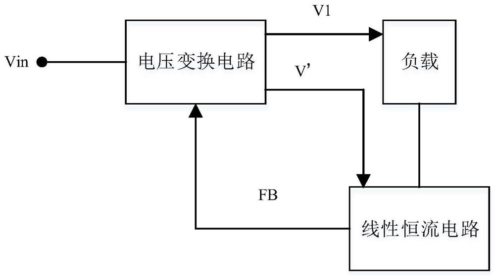
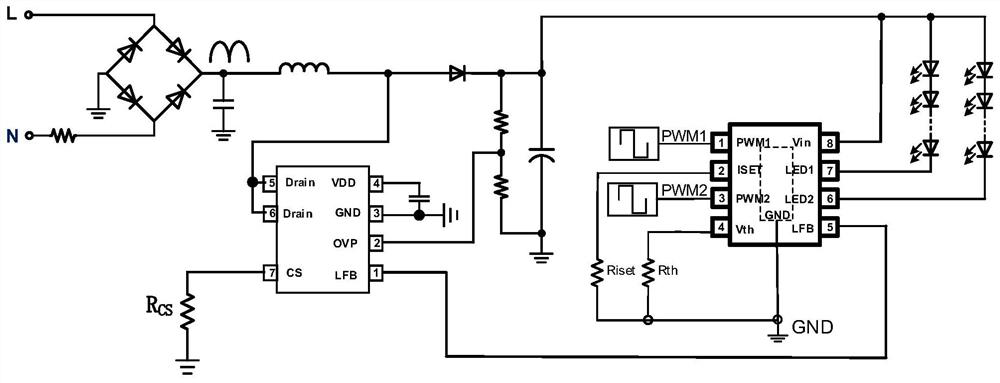
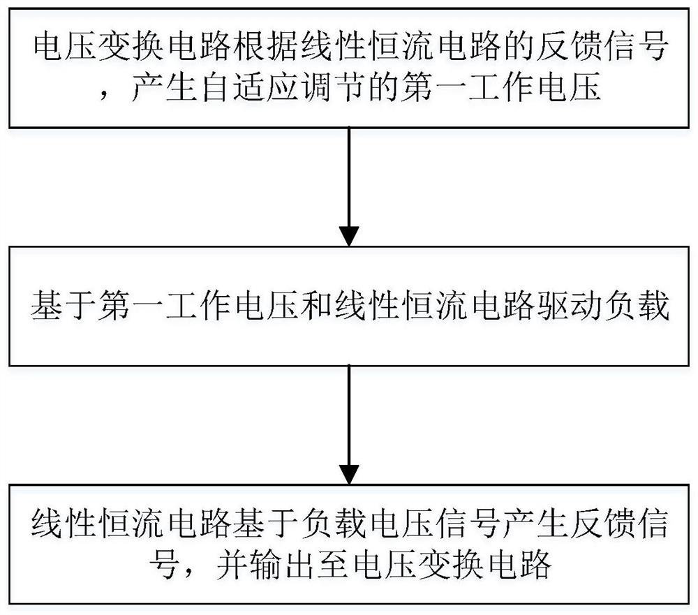
The invention provides a load driving circuit and a driving method. The load driving circuit comprises a voltage conversion circuit and a cascaded linear constant current circuit, the voltage conversion circuit is used for converting an input voltage into a first working voltage based on a feedback signal of the linear constant current circuit, and the linear constant current circuit is used as a post-stage circuit to be coupled with the voltage conversion circuit. The circuit is used for providing a driving voltage and a driving current for a load and generating a feedback signal based on a load voltage signal to control the voltage conversion circuit. According to the invention, the pre-stage boost circuit is combined with the feedback of the post-stage linear constant-current circuit so that the self-adaptive adjustment of the output voltage is realized, the overall efficiency of the system is improved, and a stable dimming and color modulation function of an LED can be realized.

Description

technical field [0001] The present invention relates to the field of electronics, specifically but not limited to a load driving circuit and a driving method. Background technique [0002] At present, LED driver chips can be divided into: constant voltage driver chips, constant current driver chips, and pulse driver chips. Among them, the constant voltage driver chips are mostly DC / DC boost chips. The advantage of this solution is that the chip cost is cheap and there is no complicated peripheral circuit. However, the constant voltage drive cannot control the drive current of the load, and cannot guarantee the consistency of LED brightness. The constant current drive chip controls the switching circuit based on the output current, which solves the problem of uncontrollable current in the previous constant voltage drive, and can flexibly set the required output current. However, the price of such chips is much higher than that of constant voltage chips and the peripheral ci...

Claims


Application Information

Patent Timeline
Patent Type & Authority Applications(China)
IPC IPC(8): H05B45/30H05B45/37H05B45/345H05B45/395H05B45/355H05B45/325H05B47/165H05B45/10H05B45/20
CPCH05B45/30H05B45/37H05B45/345H05B45/395H05B45/355H05B45/325H05B47/165H05B45/10H05B45/20Y02B20/30
Inventor 刘白仁张波
Owner SHENZHEN KIWI MICROELECTRONICS CO LTD
Why Eureka
Eureka Blog
Learn More