A mechanical fixture for mechanical automation production that facilitates automatic control of clamping force

A mechanical and strength technology, applied in the field of fixture equipment, can solve the problems of heavy objects to be processed, unclampable objects to be processed, and single function

Active Publication Date: 2022-06-21
JIANGSU VOCATIONAL INST OF ARCHITECTURAL TECH
View PDF15 Cites 0 Cited by
  • Summary
  • Abstract
  • Description
  • Claims
  • Application Information

AI Technical Summary

Problems solved by technology

The fixtures currently on the market are not only complex in structure, but also have single functions. There is no hydraulic device. Generally, the items to be processed are heavy, and the hydraulic device cannot provide a large driving force, so that the object to be processed cannot be clamped quickly, which cannot meet the needs of use. It is inconvenient to use; there is no clamping force sensor, and the required clamping force cannot be set through an external control panel, which is not smart to use; for this reason, people propose a fast tooling fixture with adjustable clamping force, such as Chinese patent 2018 A kind of publication number CN105798344B disclosed on October 12, 2010 is a fast tooling fixture with adjustable clamping force, which includes a chuck type clamp body, a small disc body and a clamping force sensor, and the external setting of the clamping force sensor is There is a hydraulic mechanical gripper, the right side of the hydraulic mechanical gripper is provided with a drilling template, and the inside of the drilling template is provided with a hydraulic device, which improves the work efficiency; it can sense the hydraulic mechanical gripper used when clamping objects The clamping force can be obtained, and the required clamping force can be set through the external control panel, and the use is intelligent and precise;
[0004] However, in the actual use process, it is difficult for traditional mechanical fixtures to clamp, move, release and select materials in an integrated manner, and often requires manual assistance or manipulation. The degree of automation is low, which brings inconvenience to use.

Method used


Image

  • A mechanical fixture for mechanical automation production that facilitates automatic control of clamping force
  • A mechanical fixture for mechanical automation production that facilitates automatic control of clamping force
  • A mechanical fixture for mechanical automation production that facilitates automatic control of clamping force

Examples


Embodiment Construction

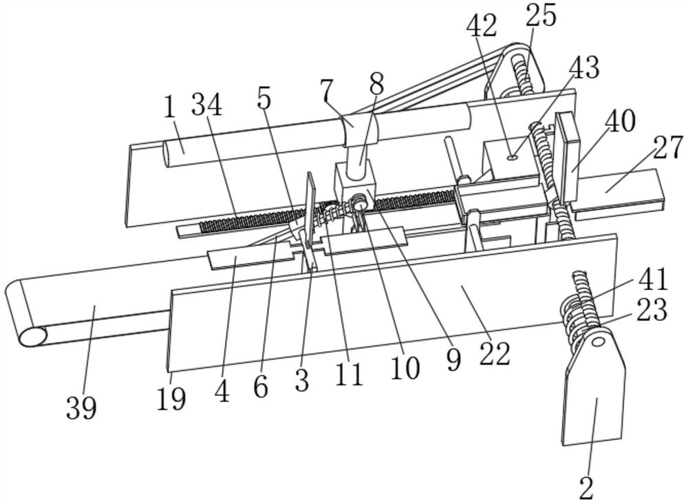
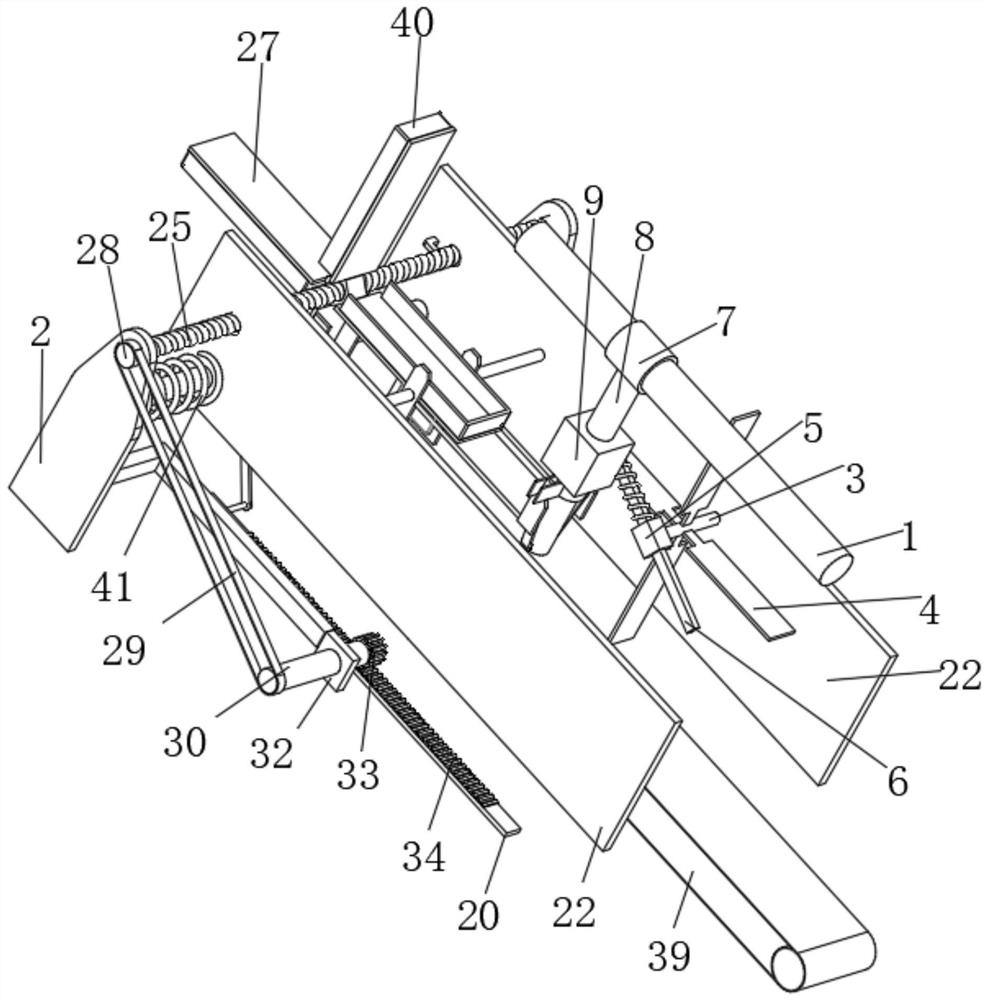
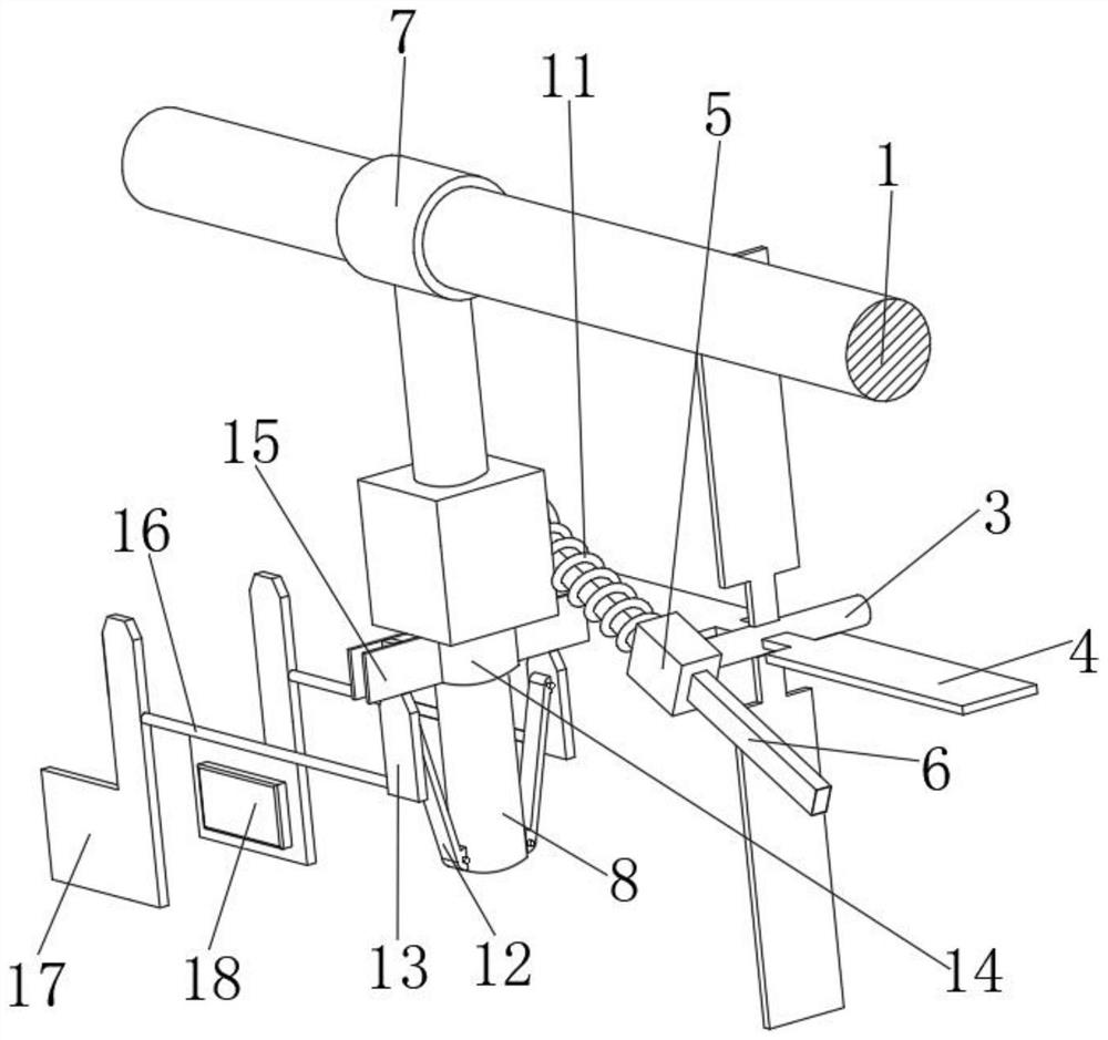
[0028] The present invention will be further described below with reference to the accompanying drawings (the left and right front and rear directions in the following description and the figure 1 The left and right front and rear directions are the same, just to describe the present invention).

[0029] like Figure 1 to Figure 6As shown in the figure, a mechanical fixture for automatic production of machinery that facilitates automatic control of the clamping force includes a cross bar 1 fixed on the frame, two support plates 2 and an output shaft 3 powered by a power mechanism. The rod 1, the support plate 2 and the output shaft 3 are arranged on the frame, so that the whole device is fixedly supported, and the fan blade 4 is fixedly connected to the arc contour of the output shaft 3, and the rotation of the output shaft 3 is driven by the power mechanism, The above-mentioned power mechanism is a motor, which is powered by an external power supply, and drives the rotation ...


PUM


Abstract

A mechanical fixture for mechanical automation production that is convenient for automatic control of the clamping force. The fan blade plate is fixed on the arc profile of the output shaft, and the front end of the output shaft is fixed to the connecting sleeve 1; the inner wall of the connecting sleeve 1 is connected to the rotating rod, and the horizontal rod is connected to the sliding Sleeve 1, the fixed vertical rod of sliding sleeve 1, the surface of the vertical rod is connected with sliding sleeve 2, the rear side of sliding sleeve 2 is fixed to the connecting seat, the inner wall of the connecting seat is connected with one end of the rotating rod through a pin shaft, and the surface of the rotating rod is covered with Provide compression spring 1, the two ends of compression spring 1 are fixedly connected with the opposite sides of connecting seat and connecting sleeve 1, the surface of the vertical bar near the bottom is connected with the rotating plate, the side of the rotating plate near the top is connected with splint 1, the surface of the vertical bar The connecting sleeve 2 is sleeved, the top of the connecting sleeve 2 is connected with the bottom of the sliding sleeve 2, the front and rear sides of the connecting sleeve 2 are fixed with limit plates, the opposite sides of the two splints 2 are connected to the airbag, and the splint 1 is provided with a dialing device to dial The feeding device is provided with a feeding device. The invention can realize automatic pick-and-place, subsequent collection and quantitative delivery of materials.

Description

technical field [0001] The invention relates to an automatic mechanical clamp, in particular to a mechanical clamp for automatic production of machinery which is convenient for automatic control of clamping force, and belongs to the technical field of clamp equipment. Background technique [0002] Fixture refers to the device used to fix the processing object in the process of mechanical manufacturing, so that it occupies the correct position to accept construction or inspection, also known as fixture. In a broad sense, any process in the process, the device used to quickly, easily and safely install the workpiece can be called a fixture. [0003] The fixture usually consists of a positioning element (determining the correct position of the workpiece in the fixture), a clamping device, a tool setting guide element (determining the relative position of the tool and the workpiece or guiding the tool direction), an indexing device (enabling the workpiece to be installed in one ...

Claims


Application Information

Patent Timeline
Patent Type & Authority Patents(China)
IPC IPC(8): B23Q3/06B23Q7/06
CPCB23Q3/06B23Q7/06
Inventor 张少鹏曾祥文肖根先伊登峰李爱民康力安淑女
Owner JIANGSU VOCATIONAL INST OF ARCHITECTURAL TECH
Why Eureka
Try Eureka