Automatic press-fitting process for flow guiding pipe

A diversion tube and automatic technology, which is applied in the field of the automatic press-fitting process of the diversion tube, can solve the problems of low degree of automation, inconvenient operation, slow press-fitting speed, etc., and achieves high degree of automation, fast press-fitting speed and adaptability. high degree of effect

Active Publication Date: 2021-08-24
CHANGZHOU BAODUN ELECTRONICS MACHINERY
View PDF6 Cites 2 Cited by
  • Summary
  • Abstract
  • Description
  • Claims
  • Application Information

AI Technical Summary

Problems solved by technology

[0002] The diversion tube is widely used in automobile manufacturing. The traditional diversion tube does not contain threads, so there is no need to consider the angle between the thread start end of the diversion joint and the main tube during the press-fitting process of the diversion joint and the main tube. However, in the new capless refueling system It is necessary to use a threaded diversion tube. For this reason, the thread starting end on the diversion joint needs to form a certain angle with the air hole on the main pipe position. The traditional threaded diversion tube needs to manually find the thread starting end before pressing during the press-fitting process. Installation, operation is inconvenient, press-fitting speed is slow, and the degree of automation is low. Even if a high-definition camera is used to find the starting point of the thread, it is easy to cause addressing errors due to metal reflections and other reasons.

Method used


Image

  • Automatic press-fitting process for flow guiding pipe
  • Automatic press-fitting process for flow guiding pipe
  • Automatic press-fitting process for flow guiding pipe

Examples


Embodiment Construction

[0042] The following description and drawings illustrate specific embodiments of the invention sufficiently to enable those skilled in the art to practice them. Other embodiments may incorporate structural, logical, electrical, process, and other changes. The examples merely represent possible variations. Individual components and functions are optional unless explicitly required, and the order of operations may vary. Portions and features of some embodiments may be included in or substituted for those of other embodiments. The scope of embodiments of the present invention includes the full scope of the claims, and all available equivalents of the claims.

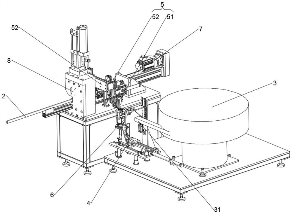
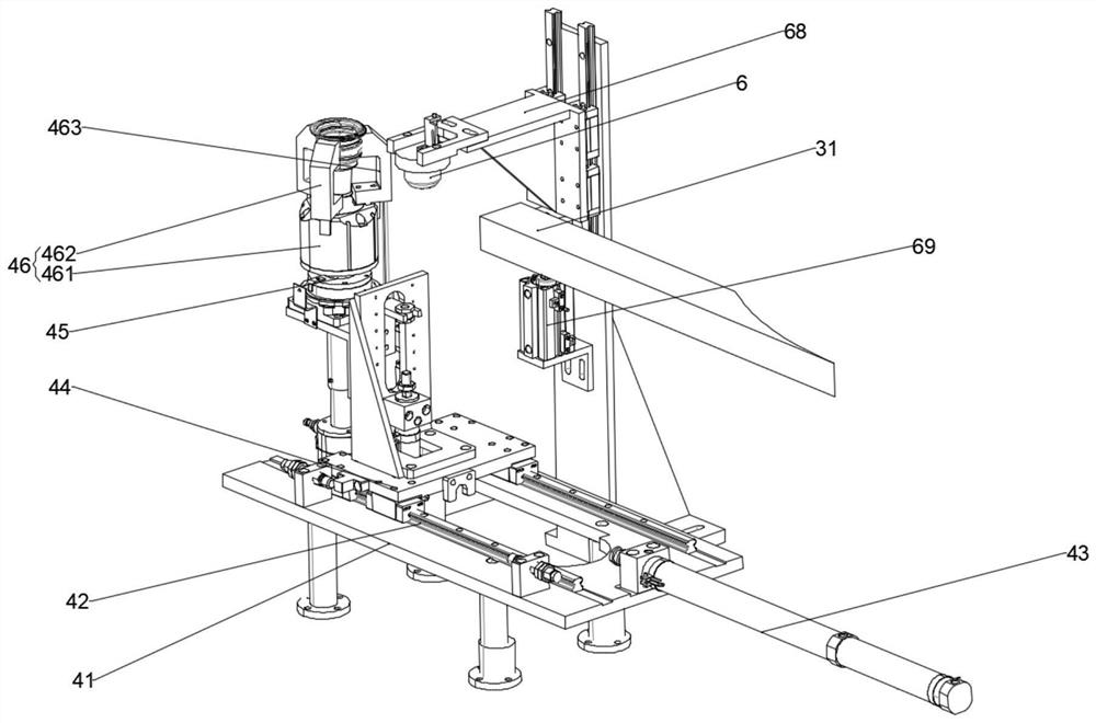
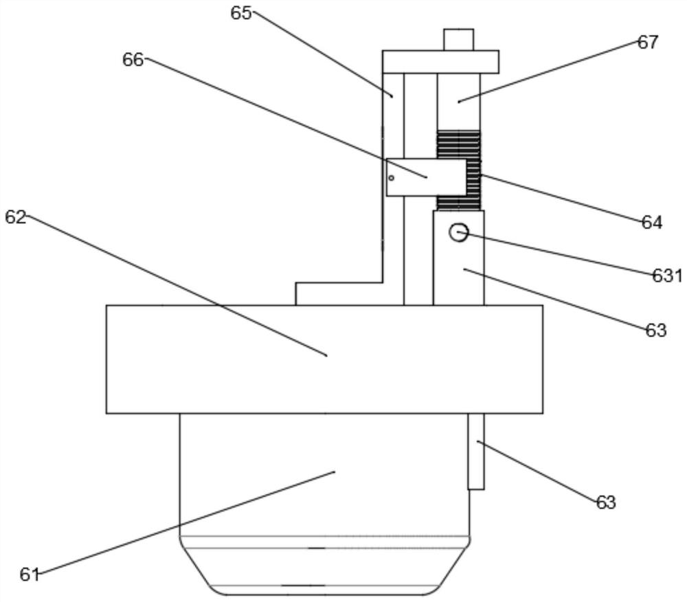
[0043] Such as Figure 1-8 As shown, an automatic press-fitting process for a draft tube,

[0044] It includes: a diversion joint 1 and a pipe body 2. The diversion joint 1 is provided with a thread 11, and the pipe body 2 is provided with a positioning air hole 21. It is characterized in that it includes the following ...


PUM


Abstract

The invention particularly relates to an automatic press-fitting process for a flow guiding pipe. The automatic press-fitting process for the flow guiding pipe is characterized by sequentially comprising the following steps that S1, a pipe body is placed in a clamping mechanism to be positioned and clamped; S2, a flow guide connector is selected out through a vibration disc; S3, a transverse moving device clamps the flow guide connector and transfers the flow guide connector to a positioning station for positioning; S4, after positioning is completed, the transverse moving device transfers the flow guide connector to a material transferring device for material transferring; S5, the material transferring device moves the flow guide connector to a press-fitting station, and a pushing motor pushes a material taking device to move forwards to sleeve the flow guide connector at the moment; S6, photographing inspection is conducted by a high-definition camera; S7, if a thread position of the flow guide connector is not qualified, an operator is prompted to conduct a reset operation to the material taking device, and the steps S2 to S6 are repeated; if the thread position is qualified, the step S8 is carried out; S8, the pushing motor pushes the material taking device to press the flow guide connector into the pipe body. The automatic press-fitting process for the flow guiding pipe is convenient automatically to find a thread starting position of the flow guiding pipe, and the beneficial effect of improving the flow guiding pipe press-fitting speed is achieved.

Description

technical field [0001] The invention relates to the field of auto parts manufacturing, in particular to an automatic press-fitting process for a draft tube. Background technique [0002] The diversion tube is widely used in automobile manufacturing. The traditional diversion tube does not contain threads, so there is no need to consider the angle between the thread start end of the diversion joint and the main tube during the press-fitting process of the diversion joint and the main tube. However, in the new capless refueling system It is necessary to use a threaded diversion tube. For this reason, the thread starting end on the diversion joint needs to form a certain angle with the air hole on the main pipe position. The traditional threaded diversion tube needs to manually find the thread starting end before pressing during the press-fitting process. Installation, operation is inconvenient, press-fitting speed is slow, and the degree of automation is low. Even if a high-de...

Claims


Application Information

Patent Timeline
Patent Type & Authority Applications(China)
IPC IPC(8): B25B27/02B65G47/90
CPCB25B27/02B65G47/90
Inventor 杜哲群韦召华
Owner CHANGZHOU BAODUN ELECTRONICS MACHINERY
Why Eureka
Try Eureka