Multi-stage telescopic rotary conveyor
A telescopic rotation, conveyor technology, applied in the direction of conveyor, transportation and packaging, can solve the problems of poor applicability, unfavorable use, poor flexibility, etc., to increase the flexibility of use, increase applicability, and increase stability.
- Summary
- Abstract
- Description
- Claims
- Application Information
AI Technical Summary
Problems solved by technology
Method used
Image

Examples
Embodiment 1
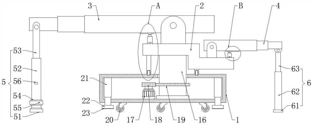
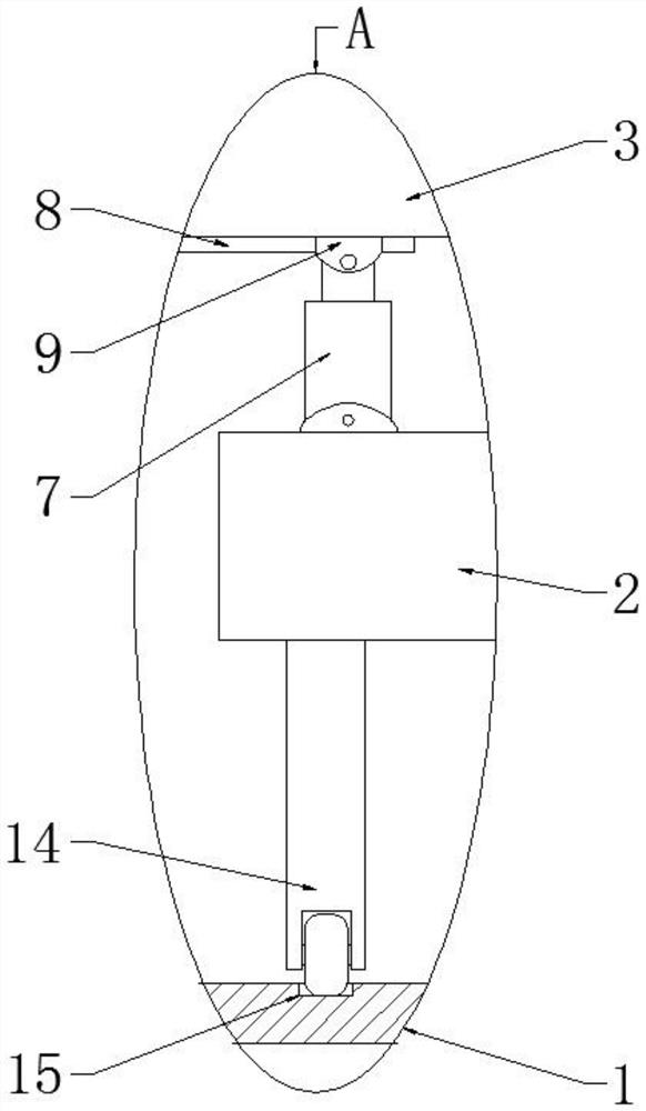
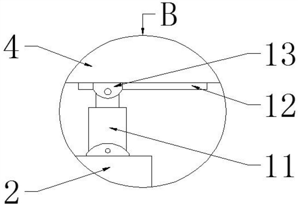
[0031] Such as Figure 1-4 As shown, a multi-stage telescopic rotary conveyor includes a bottom box 1, the inner bottom surface of the bottom box 1 is rotatably connected with a rotating shaft 16, the upper end of the rotating shaft 16 extends through the top surface of the bottom box 1 to the outside of the bottom box 1, and the rotating shaft The upper end of 16 is fixedly connected with a Z-shaped plate 2, and the top surface of the Z-shaped plate 2 is hinged with a first telescopic conveyor 3 and a second telescopic conveyor 4, and the Z-shaped plate 2 is provided with a first adjustment mechanism and a second adjustment mechanism. mechanism, the first telescopic conveyor 3 is provided with a first support mechanism 5, and the second telescopic conveyor 4 is provided with a second support mechanism 6; the first support mechanism 5 includes a first fixed plate 51 and a belt strip 55, the first Two first threaded cylinders 52 are rotatably connected to the top surface of the...
Embodiment 2
[0035] Such as Figure 1-2 As shown, under the condition that other parts are all the same as in Embodiment 1, the difference between this embodiment and Embodiment 1 is that: a driving mechanism for driving the rotating shaft 16 to rotate is arranged in the bottom case 1, and the driving mechanism includes a motor 17, and the motor 17 Installed in the bottom case 1, the power output shaft of the motor 17 is fixedly connected with a driving gear 18, and the driving gear 18 is meshed with a driven gear 19, and the driven gear 19 is fixedly sleeved on the rotating shaft 16. Driving gear 18 is stainless steel material, and driven gear 19 is also stainless steel material, and the driving gear 18 of stainless steel material, driven gear 19 can not be corroded, more durable; The top surface of bottom case 1 is provided with annular chute 15, Two rollers 14 are installed on the bottom surface of the Z-shaped plate 2 , and the lower parts of the two rollers 14 are all located in the a...
Embodiment 3
[0039] Such as figure 1 As shown, under the condition that the other parts are the same as those in Embodiment 1, the difference between this embodiment and Embodiment 1 is that: the bottom box 1 is provided with a moving mechanism and a lifting mechanism, and the moving mechanism includes a plurality of mounting brackets, and a plurality of mounting brackets. The frames are all installed on the bottom surface of the bottom box 1, and the moving wheels 20 are all installed on a plurality of mounting frames. The lifting mechanism includes a plurality of hydraulic cylinders 21, and the plurality of hydraulic cylinders 21 are installed on the inner bottom surface of the bottom box 1. The extension ends of the plurality of hydraulic cylinders 21 all pass through the bottom surface of the bottom box 1 and are slidably connected with the bottom surface of the bottom box 1. Extension ends of the plurality of hydraulic cylinders 21 are fixedly connected with support plates 22 . Gaske...
PUM
 Abstract
Description
Claims
Application Information
 - R&D
- Intellectual Property
- Life Sciences
- Materials
- Tech Scout
- Unparalleled Data Quality
- Higher Quality Content
- 60% Fewer Hallucinations
Browse by: Latest US Patents, China's latest patents, Technical Efficacy Thesaurus, Application Domain, Technology Topic, Popular Technical Reports.
© 2025 PatSnap. All rights reserved.Legal|Privacy policy|Modern Slavery Act Transparency Statement|Sitemap|About US| Contact US: help@patsnap.com