Anti-falling control method for cargo carrying platform

A control method and cargo platform technology, applied in lifting frames, lifting devices, etc., can solve the problems of high precision requirements for pre-installation and debugging of equipment, delay in starting the anti-fall mechanism, and further improvement, etc. The effect of falling activation, improving immediacy and accuracy, and significant protective effect

Active Publication Date: 2021-08-24
QINGDAO KENGIC AUTOMATION EQUIP CO LTD
View PDF5 Cites 0 Cited by
  • Summary
  • Abstract
  • Description
  • Claims
  • Application Information

AI Technical Summary

Problems solved by technology

Since the mandrel is not on the symmetrical centerline of the two guide posts that provide guidance for the slider, the force transmitted from the lever to the slider during the anti-fall start process will not be consistent with the breaking of the rope and the falling direction of the loading platform. An included angle, the force can be decomposed into the vertical force that makes the slider move up and down and the horizontal force that is vertical to the guide post, and the horizontal force increases the friction between the slider and the guide post, hindering the sliding of the slider, so When the rope breaks, there will be a certain delay in the start of the anti-fall mechanism, so the safety performance needs to be further improved
In addition, the structure of the above-mentioned lever triggering the anti-falling device is asymmetrical, and contains many parts, and the installation is relatively complicated. The pre-installation and debugging accuracy of the equipment is high, and it is easy to cause the lever to be stressed due to the heavy load of the cargo platform. Unbalanced and further delays in the start of the anti-fall mechanism obviously cause obvious constraints and application limitations to the miniaturization and refinement of existing equipment and the optimization of three-dimensional storage operations.

Method used


Image

  • Anti-falling control method for cargo carrying platform
  • Anti-falling control method for cargo carrying platform
  • Anti-falling control method for cargo carrying platform

Examples


Embodiment 1

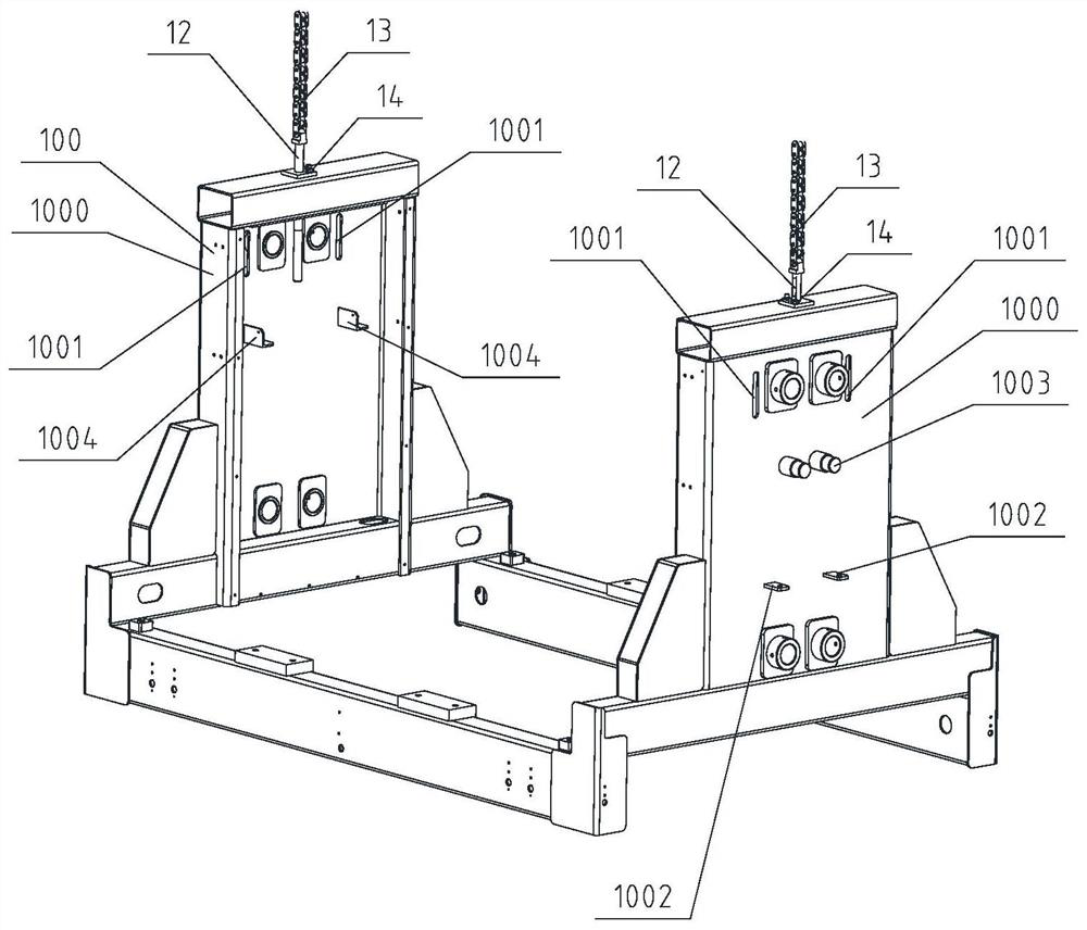
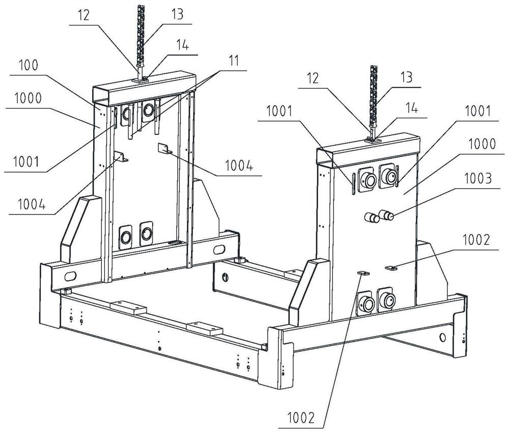
[0029] Example 1, such as Figure 1-7 As shown, the cargo platform applying the anti-fall control method described in the present application has two sets of cargo platform side arms 1000 connected to the lifting chain 13, and a set of cam-type anti-falling devices is respectively installed on each group of cargo platform side arms 1000 mechanism.

[0030] Specifically, two sets of oblong through slots 1001 , two sets of bottom positioning plates 1002 , two sets of mandrels 1003 , and two sets of upper positioning seats 1004 are installed on the cargo bed side arm 1000 . The positioning plate 1002 and the mandrel 1003 are located on the outside of the cargo platform side arm 1000 , and the upper end positioning seat 1004 is located on the inside of the cargo platform side arm 1000 .

[0031] The cam-type anti-falling mechanism includes a lifting screw 12 connected to a lifting chain 13, the lifting screw 12 runs through the top of the cargo platform side arm 1000, the upper e...


PUM


Abstract

The invention provides an anti-falling control method for a cargo carrying platform. Cam type anti-falling mechanisms symmetrically distributed along the two sides of a guide rail are designed so as to lower the requirements for pre-installation and precision debugging of the anti-falling mechanisms, improve the adaptability to the stress balance and running state of the cargo carrying platform, effectively shorten the starting interval time of the anti-falling mechanisms, and improve the stability performance of bearing equipment. When lifting chains are broken or damaged, connecting rods slide downwards along guide columns under the combined action of the gravity of the connecting rods and the return elastic force of first springs, and then detection blocks enter the sensing range of proximity switches to trigger electrical alarms. Under the driving of the connecting rods, first screw rods move downwards and push swing arms, meanwhile, the swing arms swing under the action of the reset elastic force of second springs, and cams rotate around the axial center lines of mandrels until the cams make contact with the guide rail, so that rail clamping self-locking is achieved.

Description

technical field [0001] The invention relates to an anti-fall control method of a cargo platform using a cam anti-fall mechanism, which belongs to the field of logistics storage. Background technique [0002] At present, at the operation and delivery site of the three-dimensional logistics warehouse, various types of cargo-carrying equipment that are pulled by ropes for vertical lifting are usually used, and the cargo is transported between different working heights through the cargo-carrying equipment. [0003] The load-bearing parts of the existing cargo platforms usually use steel wire ropes or lifting chains. After long-term heavy load use, there are potential safety hazards that the load-carrying parts will be partially damaged or even broken. At this time, the cargo platform will fall freely and then Serious safety accidents will occur, causing injuries to workers and other equipment in the on-site environment. [0004] For example, the domestic patent previously appli...

Claims


Application Information

Patent Timeline
Patent Type & Authority Applications(China)
IPC IPC(8): B66F7/02B66F7/28
CPCB66F7/02B66F7/28
Inventor 龙进军刘真国徐棵苗郭环
Owner QINGDAO KENGIC AUTOMATION EQUIP CO LTD
Why Eureka
Try Eureka