Message transmission method, device and system
A message transmission and message technology, applied in the network field, can solve problems such as high link load on the user side and affecting transmission quality
Pending Publication Date: 2021-08-24
HUAWEI TECH CO LTD
0 Cites 2 Cited by
AI-Extracted Technical Summary
Problems solved by technology
However, in fact, the traffic of different user terminals varies greatly. When an elephant flow occurs in the uplink traffic of a user t...
Abstract
The invention provides a message transmission method, device and system, relates to the technical field of networks, and can improve the utilization rate of a user side link and reduce the load of the user side link. The method is applied to a network architecture composed of a user terminal, a first forwarding device and a second forwarding device. A tunnel is arranged between the first forwarding equipment and the second forwarding equipment; and the message of the user terminal is forwarded to the first forwarding device and the second forwarding device in a load sharing manner. The method comprises the following steps that: first forwarding equipment receives a message forwarded by a user terminal in a load sharing manner, wherein the message comprises a keep-alive request message; the first forwarding equipment is standby forwarding equipment corresponding to the user terminal. The first forwarding device forwards the keep-alive request message to a second forwarding device through a tunnel; the second forwarding device is a main forwarding device corresponding to the user terminal.
Application Domain
Network traffic/resource managementHybrid transport +1
Technology Topic
TelecommunicationsNetwork architecture +3
Image
Examples
- Experimental program(1)
Example Embodiment
[0076] The message transmission method, apparatus, and system provided by the present application embodiment will be described in detail below with reference to the accompanying drawings.
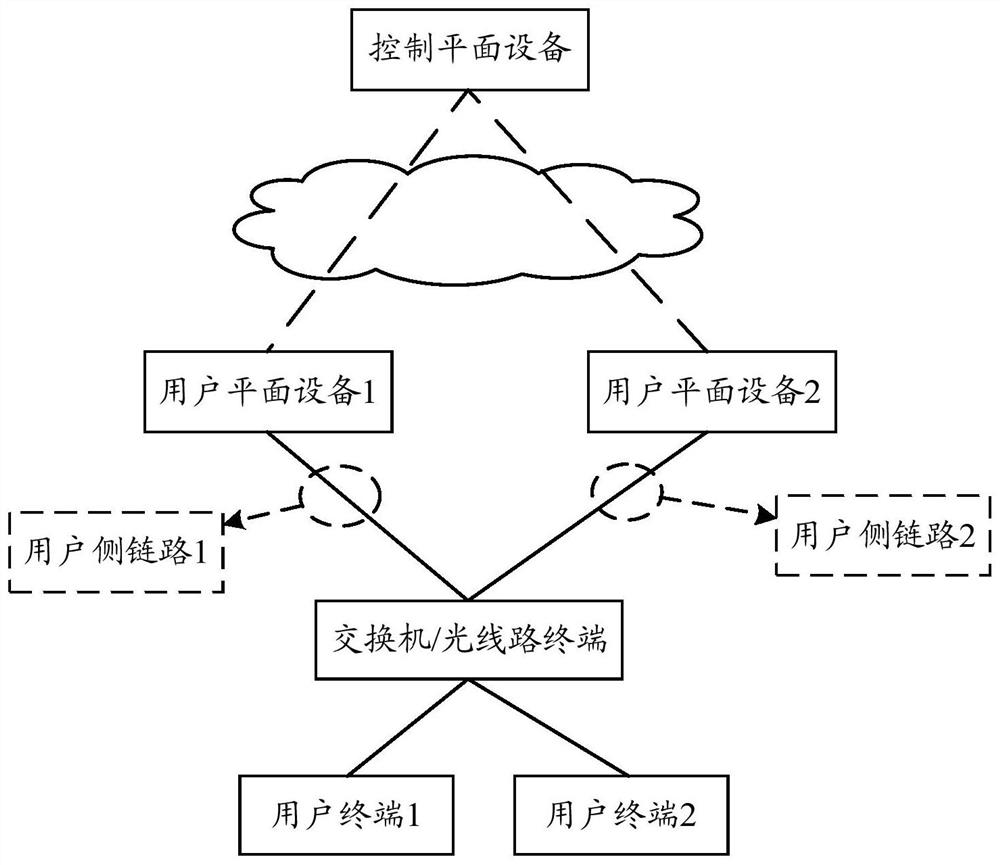
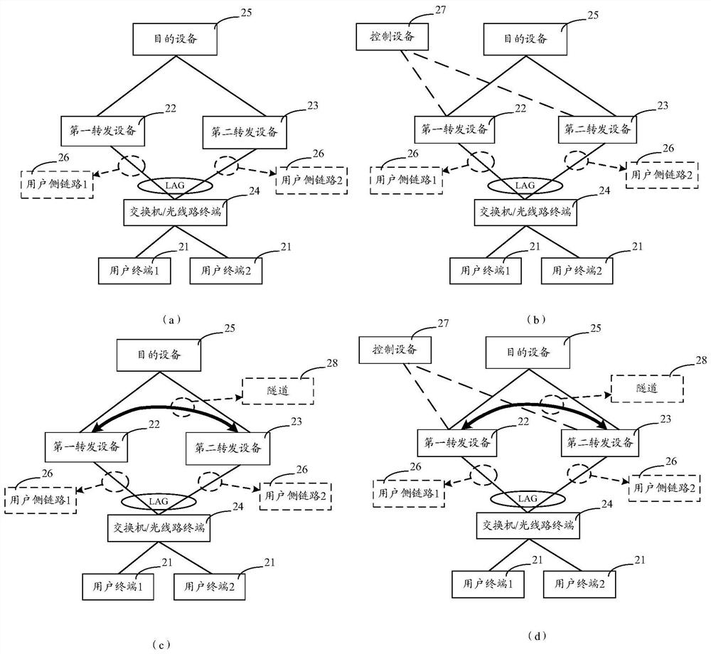
[0077] figure 2 (A) exemplary a network architecture of a message transmission system provided by the present application embodiment. The network architecture includes a plurality of user terminals 21 (e.g., user terminal 1 and user terminal 2), the first forwarding device 22, and the second forwarding device 23. Each device can be connected via a wired network or a wireless network. The connection method between the apparatus does not specifically limit the connection between the apparatus.
[0078] The user terminal 21 can be a mobile phone, a tablet, a computer with wireless transceiver, Personal Digital Assistant, PDA, smart watch, netbook, wearable electronic equipment, enhanced reality Augment Reality, AR) Equipment, Virtual Reality, VR) device, in-vehicle device, Industrial Control, wireless terminal in unmanned, remote medical (Remote MediT) Wireless terminal in Smart Grid, SmartGrid, Wireless Terminal in Transportation Safety, Wi-Fi Terminal, Smart Home, Wi-Family (SMART Home), Artificial Intelligence ( ArtificialIntelligence, AI) Terminal, etc., the terminal device of the network access function can be implemented, and the embodiment of the present disclosure does not specifically limit the specific morphology of the user terminal.
[0079] The first forwarding device 22 and the second forwarding device 23 may be, for example, a broadband access server (BRAS); or, such as figure 1 As shown, the BNG device is applied to a network architecture based on SDN and NFV, and BNG device decoupling is implemented, and the first forwarding device 22 and the second forwarding device may be a user plane (BNG-UP) device of BNG. The first forwarding device 22 and the second forwarding device 23 are located on the edge of the network layer, and the function of the bridge between the broadband access network and the backbone network provides basic access means and the management function of the broadband access network. A wide range of business aggregation and forwarding can meet the requirements of different users on transmission capacity and bandwidth utilization, and is a core device for broadband users. For example, after the first forwarding device 22 receives the user terminal 21, the message can be forwarded to the destination device 25 corresponding to the packet by a two-layer device such as SW / OLT 24. The destination device 25 can include, for example, an Internet or an external network device. As such, the user terminal 21 that can realize the broadband service is connected to the Internet via the first forwarding device 22. The first forwarding device 22 and the second forwarding device 23 can also receive packets transmitted by the devices 25, and forward the packet to the user terminal 21.
[0080] Optionally, the user terminal 21 needs to authenticate the user terminal 21 before normal accessing the network. Then, the above network architecture can also include authentication, authorization, and billing, AAA servers. The AAA server provides a server capable of handling user terminal 21, providing authentication authorization, and account services, the main purpose is to manage user terminals to access web servers, providing services for user terminal 21 with access to access.
[0081] Optional, such as figure 2 As shown in (b), if the first forwarding device 22 and the second forwarding device 23 are the user plane (BNG-UP) device of BNG, the network architecture may also include a control device 27, such as a control plane of BNG ( BNG-CP) equipment. Control device 27 is used to match authentication, billing, and management functions accessible to user terminal 21 access to authentication system, billing system, customer management system, service policy control system, and AAA server. Or, if figure 2 As shown in (a), if the first forwarding device 22 and the second forwarding device 23 are BRAS devices, the first forwarding device 22 and the second forwarding device 23 are directly used for the authentication system, billing system, customer management. The system, service policy control system, and AAA servers match authentication, billing, and management functions that implement user terminal 21 access.
[0082] Optional, such as image 3 As shown, the interface between the control device and the first forwarding device / second forwarding device is shown. Communication is implemented between the control device and the first forwarding device / second forwarding device, and communication is implemented by a Packet Redirect Interface (PRI), the State Control Interface, SCI), and the Management Interface (MI). Among them, the use of each interface in the embodiments of the present application is shown in the following Figure 4 Sum Figure 5 Description of the relevant description of the user terminal authentication process.
[0083] It should be noted that the above network architecture can be a conventional three-layer network topology, or a Leaf-SPINE network topology. Another forwarding device can be configured between the first forwarding device 22 and the second forwarding device 23 as the first forwarding device 22 and the second forwarding device 23, and another forwarding device may be configured between the first forwarding device 22 and the second forwarding device 23 and the destination device 25. Alternatively, as the development of network technology can be other types of network topologies.
[0084] In order to improve the user side link 26 between the SW / OLT 24 and the first forwarding device 22 and the second forwarding device 23 (for example figure 2 The utilization rate of the user side link 1 and the user side link 2 shown in (a) in (a) prevents a problem that the single-side link load is large. A plurality of physical secondary user side links 26 can be bundled into a logical Layer 2 link by link aggregation group, lags technology. The plurality of user side links 26 in the LAG correspond to the Sw / OLT 24 connected to the SW / OLT 24, and the plurality of user side links 26 under the TRUNK port can achieve load balancing. So, such as figure 2 (A) or figure 2 In the middle of (b), after the uplink packet transmitted by the user terminal 21 passes through the SW / OLT 24, it is transmitted through the user side link 1 and the user side link 2 to the first forwarding device 22 and the second forwarding device 23. The load sharing of the user side link 26.
[0085]At present, in the existing network architecture, the business hanging in SW / OLT24 can be special line services, such as the Layer 2 Virtual Private Network, L2VPN, three-layer virtual private network (L3VPN), etc .; For broadband services. After the user side link 26 is polymerized by LAG, the user terminal 21 of the L2VPN, L3VPN, or broadband service can be distinguished by the sub-interface of the Trunk interface, so that it has a Virtual LocaLAREA NetWork (VLAN) range.
[0086] Among them, for the L2VPN user and the L3VPN user, by configuring, the message of the user terminal 21 is forwarded to the first forwarding device 22 and the second forwarding device 23 after the SW / OLT24, the packets of the user terminal 21 (such as the application LAG technology), and the first forwarding device 22 and the second forwarding device 23. A forwarding device 22 and the second forwarding device 23 can directly forward the obtained packets directly to the purpose of the device 25, i.e., a dual activation of two user-side links 26. For broadband service users, the routes corresponding to the user terminal 21 of the broadband service can only be configured to be a single forwarding device. That is, the broadband service user terminal 21 is polymerized by the LAG technology to polymerize the user side link 26 corresponding to the first forwarding device 22 and the second forwarding device 23, the route corresponding to the user terminal 21 can only be disposed of one forwarding device. The forwarding device is a main forwarding device corresponding to the user terminal 21, and the other does not configure the route of the user terminal 21 to the alternate forwarding device corresponding to the user terminal 21. This causes the user terminal 21 of the broadband service to forward the packet to the standby forwarding device in the SW / OLT24, and the standby forwarding device cannot process the packet because the route corresponding to the user terminal 21 is not configured. The corresponding packets will be discarded directly, causing the user terminal to fail.
[0087] In view of this, a message transmission method is provided in the embodiments of the present application. figure 2 The network architecture shown in (c), or is applied to figure 2 The network architecture shown in (D). in, figure 2 (C) is based on figure 2 Improvements in the network architecture shown in (a), figure 2 (D) is based on figure 2 Improvements in the network architecture shown in (b). like figure 2 (C) or figure 2 In the middle of (D), a tunnel 28 is configured between the first forwarding device 22 and the second forwarding device 23. As such, if the backup device receives the packet forwarded by the user terminal 21, and it is confirmed that the spare forwarding device of the route corresponding to the user terminal 21 is not configured, the message can be forwarded to the main forwarding device through the tunnel 28 to avoid the user. Failure offline. The message transmission method provided by the embodiment of the present application can ensure that the broadband service user terminal is transmitted normally in the premise of transmitting messages in a manner that the user side link is loaded.
[0088] First, a simple introduction to the user terminal authentication process. like Figure 4 As shown, it is a schematic diagram of a user terminal authentication process, which can be applied to figure 2 The network architecture shown in (D).
[0089] Taking the user terminal through the Ethernet Point-to-Point-to-Point Protocol Over Ethernet, the PPPoE) Access Network as an example, its authentication process can include: discovery phase negotiation process and session phase negotiation process.
[0090] Discovery phase negotiation process includes:
[0091] Step 1, the user terminal sends a dial request for PPPoE. If the user terminal sends a PPPoE activation discovery start (PPPoE Active Discovery Initiation, Padi) packets to the first forwarding device and the second forwarding device via SW / OLT.
[0092] Step Second, the first forwarding device and the second forwarding device forward the PADI packet through the PRI to the control device.
[0093] Step 3, the control device can determine the main transfer device and the standby forwarding device according to the MAC address of the user terminal corresponding to the PADI message or the number of session (or SESSION load) of the first forwarding device and the second forwarding device. . For example, the first forwarding device corresponds to the primary forwarding device corresponding to the user terminal of the MAC address, the second forwarding device corresponding to the user terminal corresponding to the user terminal of the MAC address. For example, at this time, the number of sessions of the second forwarding device is small, and the user terminal can be accessed by the second forwarding device, and the second forwarding device is a main forwarding device corresponding to the user terminal, and the first forwarding device is a user terminal corresponding to the user terminal. Forward equipment.
[0094] Step 4. Control devices Reply to the main forwarding device Reply PPPoE activation discovery provides the PPPoE ActiveDiscovery Offer, Pado packets, and the PADO packet is allowed to establish a connection to the user terminal. Suppose at this time, the control device determines that the second forwarding device is a primary forwarding device corresponding to the user terminal, then replies to the second forwarding device to the Pado packet.
[0095] Step 5, the second terminal forwards the PADO packet to the user terminal via the SW / OLT.
[0096] Step 6. After the user terminal receives the PADO packet, send the PPPoE activation discovery request (PPPoE Active Discovery Request, Padr) packets to the control device via SW / OLT and the second forwarding device.
[0097] Step 7. After the control device receives the PADR message, the PPPoE Active Session-Confirmation, PADS packet is sent to the user terminal through the second forwarding device and the SW / OLT, and the PPPoE Active Session-Confirmation, Pads is complete, and the negotiation process of the PPPoE dial-up request discovery phase is completed.
[0098] The conversation phase negotiation process includes:
[0099] Step 1, the user terminal transmits a link control protocol (LINK Control Protocol, LCP) negotiation request to the control device via SW / OLT and the second forwarding device, which carries user terminal information (such as user name and password of the user terminal), The LCP negotiation request is used to request authentication of the user terminal.
[0100] Step 2, the control device obtains user terminal information according to the LCP negotiation request, and transmits the user terminal information to the AAA server.
[0101] Step 3, the AAA server matches the stored user terminal information, matches the received user terminal information to verify the identity of the user terminal, and verify that the passage (ie, the stored user terminal information is the same as the received user terminal information) , Send a response message to the control device.
[0102] Step 4, after the control device receives the response message, allows the user terminal to access the network, notifying the AAA server to start charging, and transmitting address information assigned to the user terminal through MI to the second forwarding device and domain name information. The second forwarding device issues address information and domain name information to the user terminal.
[0103] Step 5, the control device generates and issues user entry information to the first forwarding device and the second forwarding device via SCI.
[0104] Step 6. The second forwarding device generates user routing according to user entry information, and advertises the user routing information to other devices, and subsequent user terminals can access the network through the second forwarding device.
[0105] Wherein, the user form information includes a first instruction information, a second instruction information, an IP address of the user terminal, and the MAC address of the user terminal. Here, the first instruction information is used to indicate a backup forwarding device corresponding to the user terminal, and the second instruction information is used to indicate the main forwarding device corresponding to the user terminal. The user entry information also includes any one or more of the user terminals, the route information corresponding to the user terminal, the QoS information of the user terminal, the access control list corresponding to the user terminal (ACL) information. As shown in Table 1 below, an exemplary lists include the contents and meaning of the user table item information. The ACL information corresponding to the user terminal will display the name of the ACL template corresponding to the user terminal in the user entry information.
[0106] Table 1
[0107]
[0108] Exemplary, such as Figure 5 As shown, a schematic diagram of yet another user terminal authentication process can be applied to figure 2 The network architecture shown in (c). At this point, the first forwarding device and the second forwarding device can perform actions interact with the AAA server.
[0109] See Figure 5 As shown, the discovery phase negotiation process includes:
[0110] Step 1, the user terminal sends a dial request for PPPoE. If the user terminal sends a PADI message to the first forwarding device and the second forwarding device via the SW / OLT.
[0111] Step 2, after the first forwarding device and the second forwarding device receive the PADI packet, the primary transfusion device and the standby forwarding device are determined directly according to the MAC address of the user terminal corresponding to the PADI packet. It is assumed that the second forwarding device is determined for the primary forwarding device corresponding to the user terminal, and the second forwarding device repops the Pado packet to the user terminal.
[0112] Step 3, the second terminal forwards the PADO packet to the user terminal via the SW / OLT.
[0113] Step 4 After receiving the PADO packet, the user terminal receives the PADR packet to the second forwarding device via the SW / OLT.
[0114] Step 5, the second forwarding device receives the PADR packet After sending the PADS packet to the user terminal via the SW / OLT to complete the negotiation process of the PPPoE dial request discovery phase.
[0115] The conversation phase negotiation process includes:
[0116] Step 1, the user terminal sends an LCP consultation request to the second forwarding device via the SW / OLT.
[0117] Step Second, the second forwarding device obtains user terminal information according to the LCP negotiation request, and sends the user terminal information to the AAA server.
[0118] Step 3, the AAA server verifies the identity of the user terminal, and then send answers to the second forwarding device to the second forwarding device.
[0119] Step 4, after the second forwarding device receives the answer packet, allows the user terminal to access the network, notify the AAA server to start charging, and send the address information of the address information assigned to the user terminal via the SW / OLT to the user terminal and the domain name information.
[0120] Step 5. The second forwarding device generates user entry information and user routing.
[0121] Step 6. The main forwarding device sends user data to the standby forwarding device, indicating that the standby forwarding device is synchronized by user data. That is, the second forwarding device sends user data to the first forwarding device.
[0122] Step 7. The first forwarding device performs user data synchronization and generates the corresponding user entry information.
[0123] Subsequent, the user terminal can access the network normally.
[0124] like Image 6 As shown, after the user terminal authentication is passed, the present application provides a flow diagram of a message transmission method. The method can include S101-S103:
[0125] S101, the first forwarding device receives packets forwarded by the user terminal through the load balance, which includes a warranty request message.
[0126] Wherein, the message of the user terminal can include signaling packets, such as a KeePalive request message. During the establishment of a connection and communication between the user terminal and the forwarding device, the communication between the communication, the crash, and abnormal restart are possible. After the unexpected occurrence, if the two parties are not in time to release the connection, the other party connected will maintain the connection without knowing the peer, resulting in an abnormal connection accumulated, resulting in the consumption and waste of end system resources. Based on this, the "survival" state of the connection peer can be detected using a warranty request message.
[0127] For example, if figure 2 The user side link 26 between the SW / OLT 24 and the first forwarding device 22 and the second forwarding device 22 and the second forwarding device 23 form a logical link to achieve the load sharing of the user side link 26. . The second forwarding device 23 is the main transfer device corresponding to the user terminal 21, and the second forwarding device 23 is the main transfer device corresponding to the user terminal 21, and the second forwarding device 23 is the main transfer device corresponding to the user terminal 21, for the user terminal 21. The packets of the terminal 21 are forwarded to the first forwarding device 22 and the second forwarding device 23 in a manner in which the SW / OLT 24 is shared. When the message is at SW / OLT24, SW / OLT 24 will perform load balancing, such as Hash, etc. Thereafter, the packet is forwarded to the first forwarding device 22 and the second forwarding device 23 depending on the calculation result of the load balance.
[0128] Another example, such as figure 2 The first forwarding device 22 and the second forwarding device 22 are determined by the first forwarding device 22 and the second forwarding device 22, the first forwarding device 22 is a standby forwarding device corresponding to the user terminal 21, and the second forwarding device 23 is a main transfer device corresponding to the user terminal 21. . After verifying the identity of the user terminal 21 by the second forwarding device 23 and the AAA server, the message of the user terminal 21 is forwarded to the first forwarding device 22 and the second forwarding device 23 in the SW / OLT 24. When the message is at SW / OLT24, SW / OLT 24 will perform load balancing, such as Hash, etc. Thereafter, the packet is forwarded to the first forwarding device 22 and the second forwarding device 23 depending on the calculation result of the load balance.
[0129] As such, load balancing between multiple user-side links, the first forwarding device and the second forwarding device receive the packet after load balancing operations.
[0130] S102, the first forwarding device forwards the warrant request packet into the second forwarding device through the tunnel.
[0131] Among them, the tunnel includes any of the following or several: direct connection port channel, labelswitch path, LSP), Generic Gouting Encapsulation, GRE channel, 6th version of IP protocol paragraph (segment) Routing Version, SRV6) channel. For example, the tunnel is a direct connection port link, and the direct connection channel is established between the first forwarding device and the second forwarding device, and the transmission can be directly transmitted. For example, the above-mentioned SRV6 and other forwarding techniques are used to establish a winding tunnel between the first forwarding device and the second forwarding device, and the transmission of the packet is performed by the transfer of the intermediate equipment such as the Spine device.
[0132] Exemplary, based on the calculation result of the load balance, the message is transmitted to the first forwarding device, the first forwarding device queries the user entry information, determines the identification of the user terminal corresponding to the received packet according to the user table item information. Further, according to the identification of the user terminal, determine the backup forwarding device of the user terminal corresponding to the message according to the identity of the user terminal. If the identification bit can be set in the packet, the first forwarding device determines the corresponding instruction information according to the value of the identification bit, and then determines the active preparation state indicated by the user terminal according to the value of the identification bit. The value of the identification bit corresponds to the first instruction information, and is used to indicate a backup forwarding device for the first forwarding device for the user terminal. The standby forwarding device is not used to reply to the warranty request message, the first forwarding device is forwarded to the second forwarding device through the tunnel between the second forwarding device to the second forwarding device, by the second forwarding device This warranty request message is processed.
[0133] For example, if figure 2 The first forwarding device 22 receives the message transmitted by the user terminal 21 by the message, the first forwarding device 22 receives information transmitted by the user terminal 21, and determines that the report is not required according to the user entry information. The text is processed, but the message is forwarded through the tunnel 28 to the second forwarding device 23.
[0134] S103, the second forwarding device updates the status of the user terminal according to the warranty request packet.
[0135] The state of the user terminal can, for example, include a normal connection, a numerical value, or the like. Specifically, the general communication will establish a connection information table for saving the communication status of the peer device and sets the living timer. After the second forwarding device receives a warranty request message, confirm that the user terminal is online, reset the warranty request timer, and update the status of the user terminal to restart the timing. Further, the information of the user terminal transmission is not received by the preset time, and the second forwarding device deletes information of the user terminal in the connection information table. Correspondingly, after receiving a confirmation message of the Mechanic Request Packet, the status of the second forwarding device will be updated to ensure proper connection. It will be appreciated that the second forwarding device can also actively send a label request packet to the user terminal to confirm the state of the user terminal.
[0136] Exemplary, the second forwarding device receives the first forwarding device to update the status of the user terminal after being forwarded through the warranty request packet forwarded by the tunnel, and will be based on the user route obtained during the user terminal authentication process. The terminal sends a confirmation response to the ACKNOWLEDGE CHARACTER (ACK) message. That is, even if the route corresponding to the user terminal of the broadband service can only be configured in a single forwarding device, after transmitting to the standby forwarding device manner through the load balance, the spare forwarding device can also convert the message through the tunnel forwarding. To the main forwarding device, the main forwarding device is processed according to user routing, ensuring that the user can access it normally.
[0137] For example, if figure 2 As shown in (D), the second forwarding device 23 receives the first forwarding device 22 forwarding the warranty request message forwarded by the tunnel 28, and the state of the corresponding user terminal 21 is updated according to the warranty request packet, restart the warranty Timer, and send a response message for the user terminal 21 to confirm that the two parties are connected normally.
[0138] Thus, the message transmission method provided by the present application embodiment can be ensured by establishing a tunnel between the first forwarding device and the second forwarding device, and the user terminal can be guaranteed by the message of the user terminal through the load balance, the user terminal Normal access, it is possible to improve the utilization of the user side link, and reduce the load of the user side link.
[0139] In some embodiments, data packets are also included in packets forwarded to the first forwarding device and the second forwarding device by the user terminal through the load sharing. Also, the second forwarding device (main forwarding device) is also used to process data packets and Quality of Service, QoS), such as Figure 7 As shown, it is a further packet transmission method provided by the embodiment of the present application, which may include: S201-S204:
[0140] S201, the first forwarding device receives packets forwarded by the user terminal through the load balance, which includes the first data packet.
[0141] Wherein, the message of the user terminal can also include data packets, such as flow data that can be uploaded or downloaded by the user terminal, and the traffic statistics of the data packet refers to the traffic through the situation, and obtain real-time traffic. data. QoS Processing is a network traffic management capability that can provide better or special services for some users and / or applications to deteriorate other users or applications. User traffic level can be used to use QoS processing technology. Further, QoS processing can provide different service quality for different needs of various user terminals. For example, provide dedicated bandwidth, reduce packet loss rate, network congestion management, network congestion avoidance, flow rate limit, etc., realize more reasonable allocation and utilization with existing bandwidth. If the normal home broadband user terminal requires the Internet speed to reach 300.0Mbps to meet the user's demand, the data packet corresponding to the user terminal can limit the speed limit processing, restrict the bandwidth of the assigned, and allocate more bandwidth to the delay requirements. Higher device.
[0142] Exemplary, the forwarding device can be used to flow traffic statistics and QoS processing on the message data transmitted by the user terminal, so that after the first forwarding device receives the user terminal, the user terminal is transmitted after the SW / OLT is transmitted. The user entry information will be queried to determine whether the forwarding device itself is required to forward the message for the active preparation status of the user terminal of the current transfer message.
[0143] The remainder can refer to the related description of step S101, and details will not be described herein.
[0144] S202, the first forwarding device forwards the first data packet through the tunnel to the second forwarding device.
[0145] Exemplary, the first forwarding device determines that after the user terminal of the current transmission message is the standby forwarding device, the received message data will be forwarded through the straight tunnel or bypass tunnel between the second forwarding device to The second forwarding device is processed by the second forwarding device.
[0146] The remainder can refer to the related description of step S102, and details will not be described herein.
[0147] S203, the second forwarding device receives the second data message of the user terminal.
[0148] Exemplary, the user terminal transmits data packets to forwarding devices by load, and the first forwarding device and the second forwarding device receive some of the data packets therein, so that the traffic data is transmitted in a single user-side link transmission. The user side link load is uneven, such as user-side link 1 overload, the user side link 2 load rate is insufficient, etc.
[0149] S204, the second forwarding device forwards the flow statistics and QoS processing to the first data packet and the destination device of the first data packet and the second data packet according to the first data packet and the second data packet.
[0150] Exemplary, the second forwarding device obtains a complete data packet transmitted by the user terminal by the first data packet and the second data message by the above step S202 step S203, and can be obtained by the user terminal transmission, and it can be performed on the complete data packet. Traffic statistics and QoS processing. Thereafter, the processing completed flow data forwarded to the destination device corresponding to the first data message and the second data packet. Further, the second forwarding device is also used to receive the backhaul data packets issued by the purpose, and forward the backhaul data packet to the user terminal according to the obtained user route. If a target device can be an Internet, the second forwarding device is forwarded to the Internet after the received complete data packets such as traffic data. And forward the return traffic to the user terminal. As such, the user terminal is on, and the network is connected.
[0151] For example, if figure 2The second forwarding device 23 receives the first data packet forwarded by the first forwarding device 22 through the tunnel 28, and the second data packet received by the user terminal 21, according to the first data report. After the text and second data packets perform flow statistics and QoS processing, it forwards it to the purpose of the device 25. Further, the backhaul data packet transmitted by the destination device 25 is received by the second forwarding device 23, and the second forwarding device 23 is forwarded to the user terminal 21.
[0152] Thus, the packet transmission method provided by the present application embodiment can ensure that the user terminal is transmitted by the user terminal through the load balance between the user terminal, by establishing a tunnel between the first forwarding device and the second forwarding device. Access enhances the utilization of the user side link to reduce the load of the user side link.
[0153] In some embodiments, if the user terminal is forwarded to the first forwarding device and the second forwarding device forward, the second forwarding device (main forwarding device) is not used for data. If the packet is subjected to traffic statistics and QoS processing, Figure 8 As shown, it is a further packet transmission method provided by the embodiment of the present application, which may include: S301-S303:
[0154] S301, the user terminal forwards packets to the first forwarding device and the second forwarding device through the load balance, which includes data packets.
[0155] Exemplary, the functionality of the traffic statistics and the QoS processing is not configured at the forwarding device, such as traffic statistics and QoS processing configured at SW / OLT. It is not necessary to perform traffic statistics and QoS processing on the data packets uplink on the user terminal again at the forwarding device. Where the user terminal transmits data packets through the load balance, the first forwarding device receives the first data packet, and the second forwarding device receives the second data message.
[0156] S302, the first forwarding device forwards the first data packet directly to the destination device of the first data message.
[0157] S303, the second forwarding device forwards the second data packet directly to the destination device of the second data message.
[0158] Exemplary, in step S302 and step S303, the first data packets received by the first forwarding device and the second data packets received by the second forwarding device are all on-line data packet traffic statistics and QoS. Packets transmitted in the manner after processing. As such, the first forwarding device does not have to forward the received data packet through the tunnel to the second forwarding device, and the second forwarding device does not have to wait until the data packets received by the first forwarding device forwarded data packets will be processed. . The first forwarding device and the second forwarding device can forward the received data packets to the destination device of the data packet. The destination device will determine the corresponding main forwarding device according to the data packet, and then use the main forwarding device to forward the backhaul data packet.
[0159] Thus, the packet transmission method provided by the present application embodiment can ensure that the user terminal is transmitted by the user terminal through the load balance between the user terminal, by establishing a tunnel between the first forwarding device and the second forwarding device. Access enhances the utilization of the user side link to reduce the load of the user side link.
[0160] Figure 9 A possible structure diagram of the packet transmission device according to the above embodiment is shown. The message transmission device 900 includes a receiving unit 901 and a transmitting unit 902.
[0161] Wherein, the receiving unit 901 is configured to support the message transmission device 900 Image 6 Step S101 in Figure 7 Step S201 in Figure 8 Step S301, and / or other processes for the techniques used herein.
[0162] The transmitting unit 902 is configured to support the message transmission device 900 Figure 4 Second, the step two of the consensus process is found, Image 6 Step S102, Figure 7 Step S202 in Figure 8 Step S302, and / or other processes for the techniques described herein.
[0163] The message transmission device 900 can also include a processing unit 903 for supporting the message transmission device 900 execution. Figure 5 Second, the step two of the consensus process is found, Figure 5 Step 7, and / or other processes for the techniques described herein.
[0164] The above method embodiments all the related contents of each step can be argued to the functional description of the corresponding functional unit, and details are not described herein again.
[0165] Figure 10 A possible structure diagram of the packet transmission device according to the above embodiment is shown. The message transmission device 1000 includes a receiving unit 1001 and a processing unit 1002.
[0166] Wherein, the receiving unit 1001 is configured to support the message transmission device 1000 Figure 7 Step S203 in Figure 8 Step S301, and / or other processes for the techniques used herein.
[0167] Processing unit 1002 for supporting the message transmission device 1000 Figure 4 Step 6 of the consecutive session stage Figure 5 Second, the step two of the consensus process is found, Figure 5 Step 5 for the interrogation in the session stage, Image 6 Step S103, Figure 7 Step S204, and / or other processes for the techniques used herein.
[0168] The message transmission device 1000 can also include a transmitting unit 1003 for supporting the message transmission device 1000 execution. Figure 4 Steps two and steps in the consensus process in the phase of the stage, Figure 5 Step 6 of the consecutive session stage Figure 8 Step S303, and / or other processes for the techniques described herein.
[0169] The above method embodiments all the related contents of each step can be argued to the functional description of the corresponding functional unit, and details are not described herein again.
[0170] Figure 11 The schematic diagram of the hardware structure of the packet transmission device provided in the present application embodiment. The message transmission device can correspond to the above Figure 9 The message transmission device or may correspond to the above Figure 10 The message transmission device, including at least one processor 1101, communication line 1102, memory 1103, and at least one communication interface 1104. The memory 1103 can also be included in the processor 1101.
[0171] Processor 1101 can be a universal center processor (CPU), a microprocessor, a specific application integrated circuit (ASIC), or one or more, or one or more, for controlling this application program execution. integrated circuit.
[0172] Communication line 1102 can include a passage, transmitting information between the components.
[0173] Communication interface 1104 is used to communicate with other devices. In the present application embodiment, the communication interface can be a module, a circuit, a bus, an interface, a transceiver, or other means capable of implementing a communication function for communicating with other devices. Optionally, when the communication interface is a transceiver, the transceiver can be a stand-alone sender, which can be used to send information to other devices, which can also be a stand-alone receiver for use in other The device receives information. The transceiver may also be a component that integrates the transmission, receive information, and the specific implementation of the transceiver is not limited.
[0174] Memory 1103 can be a read-only memory (ROM) or other type of static storage device that can store static information and instructions, random access memory (RAMAM Access Memory, RAM) or other types of storage information and instructions. Dynamic storage devices, can also be electrically erasable programmable read-only memory, compactdisc read-only memory, CD-ROMs, or other disc storage, CD storage (including Compressed CD, laser disc, disc, digital universal disc, blue disc, etc.), disk storage medium or other magnetic storage device, or can be used to carry or store desired program code with instruction or data structure form and can be accessed by computer Any other media, but is not limited thereto. The memory can be independently present, and the processor 1101 is connected to the processor 1101 via communication line 1102. Memory 1103 can also be integrated with processor 1101.
[0175] The memory 1103 is configured to store a computer execution instruction for implementing the present application schedule, and is controlled by processor 1101. The processor 1101 is configured to perform a computer execution instruction stored in the memory 1103, thereby implementing the packet transmission method provided by the following examples described below.
[0176] Optionally, the computer execution instruction in the present application embodiment may also be referred to as application code, instructions, computer programs, or other names, the present application embodiments do not specifically limit.
[0177] In a specific implementation, as an embodiment, processor 1101 can include one or more CPUs, such as Figure 11 CPU0 and CPU1.
[0178] In a specific implementation, as an embodiment, the message transmission device 1100 can include a plurality of processors, such as Figure 11 The processor 1101 and processor 1105 are in the processor 1105. Each of these processors can be a single-core processor, or a multi-core processor. The processor here can refer to a process core for one or more devices, circuits, and / or for processing data (eg, computer program instructions).
[0179] It should be noted that the above-described message transmission device may be a general purpose device or a dedicated device, and the present application embodiment does not limit the type of the message transmission device. The structure of the present application example does not constitute specific definitions of the message transmission device. In other embodiments of the present application, the message transmission device can include a component, or a partial component, or a different component, or a different component, or different components, or different components, or different components, or different components, or different components, or different components, or different components, or different components, or different components, or different components. The components illustrated can be implemented in hardware, software, or software and hardware.
[0180] The present application provides a packet transmission system 1200, such as Figure 12 As shown, the user terminal 1201, the first forwarding device 1202, and the second forwarding device 1203, the first forwarding device 1202 and the second forwarding device 1203 are provided with a tunnel 1204, and the packets of the user terminal 1201 pass through the load balance ( Forward to the first forwarding device 1202 and the second forwarding device 1203 using the LAG technology.
[0181] Where the first forwarding device 1202 is used to execute Image 6Steps S101 and S102 in Figure 7 Steps S201 and S202 in Figure 8 Step S302, and / or other processes for the techniques described herein.
[0182] Second forwarding device 1203 is used to execute Image 6 Step S103, Figure 7 Steps S203 and S204 in Figure 8 Step S303, and / or other processes for the techniques described herein.
[0183] It will be appreciated that in the message transmission system 1200, it is possible to include more or less components, or in combination, or some components, or different components. The components illustrated can be implemented in hardware, software, or software and hardware. All related contents of the steps involved in the above method embodiments can be argued to the functional description of the corresponding components, and will not be described herein.
[0184] The present application also provides a chip system, such as Figure 13 As shown, the chip system includes at least one processor 1301 and at least one interface circuit 1302. Processor 1301 and interface circuit 1302 can be interconnected by a line. For example, interface circuit 1302 can be used to receive signals from other devices. For example, the interface circuit 1302 can be used to transmit signals to other devices (e.g., processor 1301). Exemplary, interface circuit 1302 can read instructions stored in the memory and transmit the instruction to processor 1301. When the instruction is executed by the processor 1301, each of the steps in the packet transmission method in the above embodiment can be performed. Of course, the chip system can also include other discrete devices, and the present application is not specifically limited.
[0185] The present application embodiment also provides a computer readable storage medium that stores a computer instruction in the computer readable storage medium, when the computer instruction is running on the server, so that the server performs the above-described correlation method step to implement the report in the above embodiment Text transmission method.
[0186] The present application embodiment also provides a computer program product that causes the computer to perform the above-described related steps to implement the above-described related steps when the computer program product is running on the computer.
[0187] Further, the embodiment of the present application also provides a device, which can be specifically a component or module, which can include a connected one or more processors and a memory; wherein the memory is used to store computer programs, one or more Computer programs include instructions. When the instruction is performed by one or more processors, the means transmission method in each of the above method embodiments is performed.
[0188] The apparatus, computer readable storage medium, computer program product or chip is provided by the apparatus, and the computer readable storage medium, computer program product or chip is used to perform the corresponding methods provided above, and therefore, the beneficial effects that can achieve can be referred to as provided above. The beneficial effects in the corresponding method are not described herein.
[0189] Through the description of the above embodiments, those skilled in the art can clearly understand that the convenient and concise description are described, and only the above functional modules will be described. In the actual application, the above function is allocated as needed. Different from different functional modules, the internal structure of the device is divided into different functional modules to complete all or part of the above described above. The specific operation of the system, apparatus, and unit described above can refer to the corresponding process in the foregoing method embodiment, and details are not described herein again.
[0190] In several embodiments provided herein, it should be understood that the disclosed methods can be implemented in other ways. For example, the embodiment described above is merely schematic, for example, the division of the module or unit is only one logical function division, and there may be additional division mode, such as a plurality of units or components. Binding or can be integrated into another, or some features can be ignored, or not executed. Another point, the coupling or direct coupling or communication connection between the displayed or discussed may be an electrical, mechanical or other form in an indirect coupling or communication connection of some interfaces, modules, or units.
[0191] The unit as the separation member may be or may not be physically separated, and the components displayed as the unit may be or may not be a physical unit, i.e., in one place, or can be distributed to a plurality of network elements. The object of the present embodiment can be implemented in accordance with the actual needs to select some or all units.
[0192] Further, each of the functional units in the various embodiments of the present application may be integrated into one processing unit, or each unit can be generated separately, or two or more units can be integrated into one unit. The above-described integrated units can be implemented in the form of hardware, or may be implemented in the form of a software functional unit.
[0193] The integrated unit can be stored in a computer readable storage medium if implemented in the form of a software functional unit and is sold or used as a stand-alone product. Based on this understanding, the technical solution of the present application essentially ors a portion of the prior art or all or part of the technical solution can be embodied in the form of software products, the computer software product is stored in a storage medium. While including a number of instructions for a computer device (can be a personal computer, server, or network device, etc.) or processor to perform all or some steps of the method of each of the embodiments of the present application. The aforementioned storage medium includes: flash memory, mobile hard disk, read-only memory, random access memory, disk, or optical disk, which can store program instructions.
[0194] As described above, only the specific embodiments of the present application, but the scope of the present application is not limited thereto, any change or replacement within the scope of the present application, should be covered within the scope of the present application . Therefore, the protection of the present application should be based on the scope of protection of the claims.
PUM


Description & Claims & Application Information
We can also present the details of the Description, Claims and Application information to help users get a comprehensive understanding of the technical details of the patent, such as background art, summary of invention, brief description of drawings, description of embodiments, and other original content. On the other hand, users can also determine the specific scope of protection of the technology through the list of claims; as well as understand the changes in the life cycle of the technology with the presentation of the patent timeline. Login to view more.