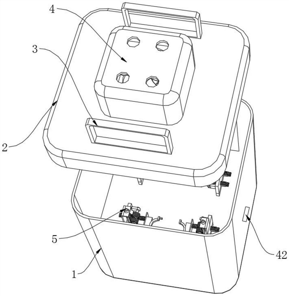
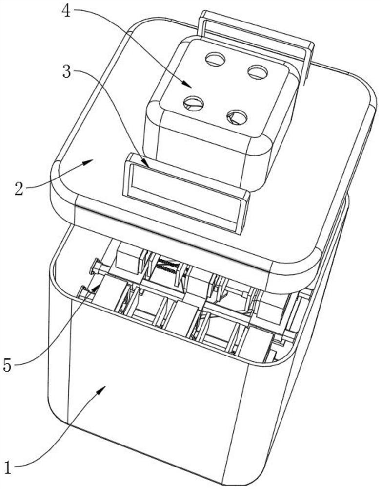
Multifunctional storage tank
A storage tank, multi-functional technology, applied in the direction of shock-sensitive items, types of packaging items, special packaging items, etc., can solve structural limitations, inconvenient automatic anti-shake clamping of milk powder tanks, falling off and damage of milk powder tanks during storage, etc. Problems, to achieve good storage effect, improve the effect of convenience
- Summary
- Abstract
- Description
- Claims
- Application Information
AI Technical Summary
Problems solved by technology
Method used
Image
Examples
Embodiment 1
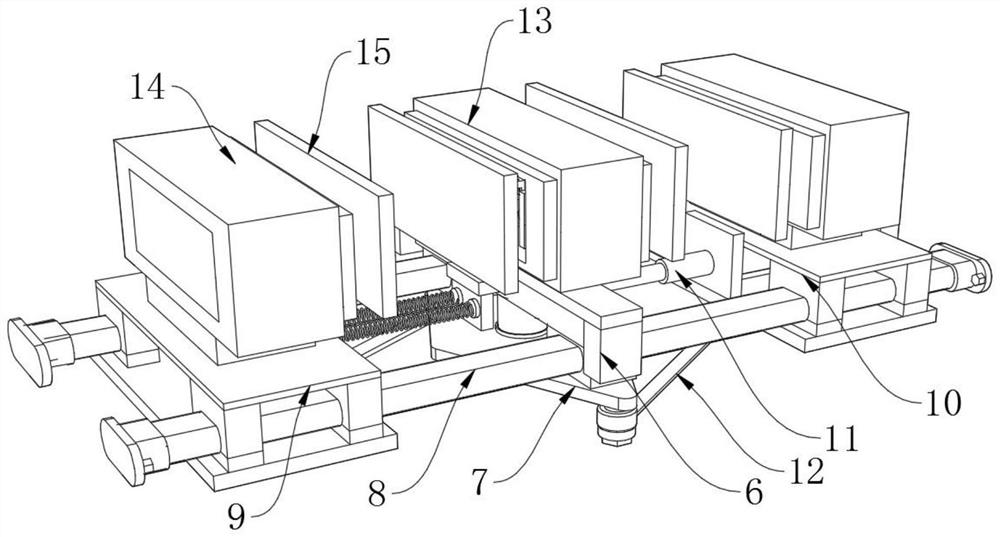
[0029] see Figure 3-4 , used to implement specific placement and positioning of square milk powder cans, specifically:
[0030] Placement and clamping structure 5 includes two-way support force beam 6, two-way synchronous linkage plate 7, auxiliary guide slide bar 8, first following derivation clamping block 9 and second follow derivation clamping block 10, two-way support force beam 6 The two ends are fixedly connected with auxiliary guiding slide bars 8, and the bottom end of the two-way supporting force beam 6 is welded and connected with a two-way synchronous linkage plate 7 through the extension of the rotating shaft. Clamping block 9, the outer side of another auxiliary guiding slide bar 8 is slidably connected with a second following derivation clamping block 10;
[0031]The clamping structure 5 also includes a first hydraulic piston cylinder 11, a linkage tension rod 12, a first central unloading clamp 13, a second central unloading clamp 14, an elastic support anti-...
Embodiment 2
[0036] see Figure 5 , on the basis of the first embodiment above, the placement of the square milk powder can is changed to the placement of the cylindrical milk can, specifically:
[0037] The placing and clamping structure 5 includes a guide mounting plate 22, an L-shaped mounting plate 23, a second hydraulic piston cylinder 24, a dynamic guide output rack 25, a limit guide slide plate 26, a fixed mounting frame 27 and a linkage rotating shaft 28, and the guide mounting plate 22 The top end of the L-shaped mounting plate 23 is fixed, and the top of the L-shaped mounting plate 23 is fixedly connected with a second hydraulic piston cylinder 24 by screws, and the output end of the second hydraulic piston cylinder 24 is fixedly connected with a dynamic guide output rack 25, and the dynamic guide The output rack 25 is slidingly connected with the guide carrying plate 22, and the both sides of one end of the guide carrying plate 22 are welded with a fixed mount 27, and the inner ...
Embodiment 3
[0041] see Image 6 :
[0042] The air-cooled constant temperature storage structure 4 includes an air circulation pipe 33, a circulation mounting base 34, an overcurrent contact temperature conducting plate 35, a semiconductor refrigeration plate 36, a first dust-proof filter plate 37, a second dust-proof filter plate 38, and a circulating wind fan 39. Fixed sealing cover plate 40 and air leakage through hole 41, the top of air circulation pipe 33 is fixedly connected with fixed sealing cover plate 40, and the top of fixed sealing cover plate 40 is provided with a plurality of air leakage through holes 41, the inside of air circulation pipe 33 From top to bottom, a circulating wind fan 39, a second dust-proof filter plate 38, a first dust-proof filter plate 37, a semiconductor refrigeration plate 36, an overcurrent contact heat conducting plate 35 and a circulation carrying base 34 are fixedly connected in sequence;
[0043] The inside of the first dust-proof filter plate 37...
PUM
 Abstract
Description
Claims
Application Information
 - R&D
- Intellectual Property
- Life Sciences
- Materials
- Tech Scout
- Unparalleled Data Quality
- Higher Quality Content
- 60% Fewer Hallucinations
Browse by: Latest US Patents, China's latest patents, Technical Efficacy Thesaurus, Application Domain, Technology Topic, Popular Technical Reports.
© 2025 PatSnap. All rights reserved.Legal|Privacy policy|Modern Slavery Act Transparency Statement|Sitemap|About US| Contact US: help@patsnap.com


