A fully automatic displacement and strain sensor calibration device

A strain sensor and calibration device technology, applied to measurement devices, optical devices, instruments, etc., can solve the problems of incomplete effective use, difficult adjustment, troublesome assembly and disassembly, etc., and achieve multi-position continuous and rapid measurement, simple adjustment, Easy to install and remove

Active Publication Date: 2022-05-17
NAT INST OF METROLOGY CHINA
View PDF6 Cites 0 Cited by
  • Summary
  • Abstract
  • Description
  • Claims
  • Application Information

AI Technical Summary

Problems solved by technology

Most of the existing calibration devices for displacement and strain sensors can only be aimed at specific types and sizes of displacement sensors. The functions are relatively single, they cannot be fully and effectively utilized, and they are troublesome to assemble and disassemble.
Difficult to adjust when measuring and calibrating

Method used


Image

  • A fully automatic displacement and strain sensor calibration device
  • A fully automatic displacement and strain sensor calibration device
  • A fully automatic displacement and strain sensor calibration device

Examples


Embodiment 1

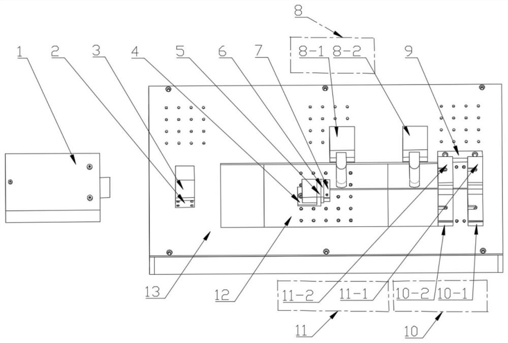
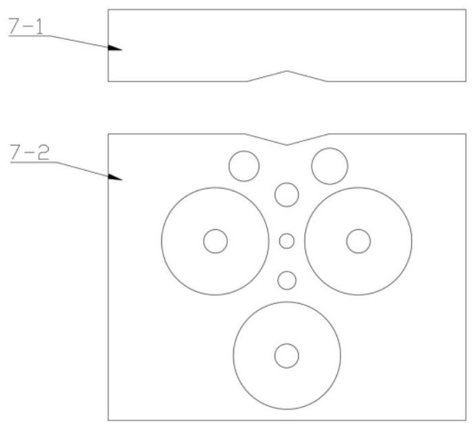
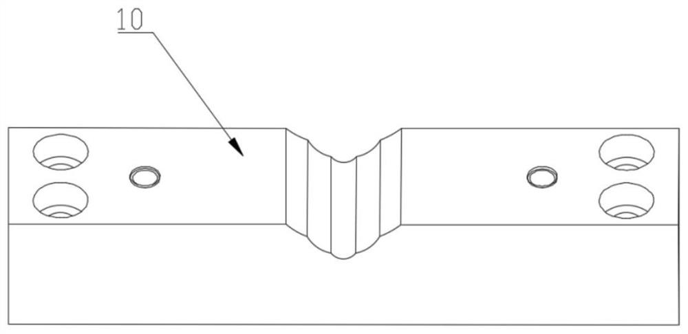
[0032] The present invention provides a fully automatic calibration device for displacement and strain sensors, including a laser 1, a spectroscopic mirror mounting plate 2, a spectroscopic mirror 3, a measuring mirror mounting plate 4, a measuring mirror 5, a fixture connector 6, a movable fixture 7, a microscope 8, Positioning bar 9 , sensor clamping block 10 , sensor clamping upper cover 11 , precision positioning table 12 , precision positioning table cover 13 .

[0033] In this embodiment, a marble horizontal work platform is adopted, and the precision positioning table 12 is fixed on the marble horizontal work platform by screws, and the precision positioning table cover 13 is fixed on the marble horizontal work platform by screws, and the precision positioning table 12 is covered and protected. stand up. The motion platform of the precision positioning table 12 is positioned in the middle of the top rectangular groove of the precision positioning table cover 13 .

[00...

Embodiment 2

[0039] In this embodiment, the sensor under test is an optical fiber strain sensor, and the optical fiber of the optical fiber strain sensor is marked. One end of the optical fiber strain sensor is fixed on the fixed fixture, and the other end is fixed on the movable fixture. And make it possible to observe the marks on the optical fiber on the two microscopes respectively.

[0040] In this embodiment, the precision positioning table 12 can be fully automatically controlled by a computer. The computer controls the motion platform of the precision positioning table 12 to move precisely, and collects the moving distance of the optical fiber marks on the two microscopes at the same time. strain as the standard strain. The readings measured by the fiber optic strain sensor are collected as measured strain. After measuring a certain distance and a certain number of times, compare the standard strain with the measured strain to calculate the basic error, linearity error, repeatab...


PUM


Abstract

The invention discloses a fully automatic calibration device for displacement and strain sensors, which belongs to the field of test and measurement. Including laser, beam splitter mounting plate, beam splitter, measuring mirror mounting plate, measuring mirror, fixture connector, movable fixture, microscope, positioning bar, sensor clamping block, sensor clamping upper cover, precision positioning table, precision positioning table cover shell. The laser, beam splitter mounting plate, beam splitter, measuring mirror mounting plate, and measuring mirror together constitute a precision displacement measurement system, which is fixed on one side of the device. The movable fixture is fixed on the measuring mirror mounting plate through the fixture connecting piece. The sensor clamping block and the sensor clamping upper cover constitute a fixed fixture, and are fixed on the precision positioning table cover by positioning strips. The microscope is fixed on one side of the precision positioning stage cover. The precision positioning table is covered and protected by the precision positioning table cover. The invention can realize full-automatic, high-precision and rapid calibration of displacement and strain sensors.

Description

technical field [0001] The invention relates to the technical field of test and measurement, in particular to a fully automatic calibration device for displacement and strain sensors. Background technique [0002] Displacement sensor, also known as linear sensor, is a linear device that belongs to metal induction. It can convert the measured physical quantity into electrical signal output, and is often used for the measurement of length and dimension. Displacement sensors are widely used in machine tool processing, transportation, construction bridges and other industries. However, during the use of the displacement sensor, with the passage of time or changes in temperature, the characteristics of the displacement sensor may change, resulting in zero point drift and other phenomena, which will reduce the measurement accuracy. In order to ensure the measurement accuracy and reliability of the displacement sensor, it is necessary to regularly Calibrate the displacement sensor...

Claims


Application Information

Patent Timeline
Patent Type & Authority Patents(China)
IPC IPC(8): G01B11/02G01B11/16
CPCG01B21/042G01B11/02G01B11/18G01B11/161
Inventor 崔建军张鹏陈恺
Owner NAT INST OF METROLOGY CHINA
Why Eureka
Try Eureka