Industrial robot cleaning equipment

A technology for industrial robots and cleaning equipment, which is applied in the direction of cleaning methods using tools, cleaning methods and utensils, chemical instruments and methods, etc., can solve problems affecting work efficiency, troublesome cleaning of robots, etc., and achieve the effect of improving work efficiency

Inactive Publication Date: 2021-08-31
泉州市智沃网络科技有限公司
View PDF0 Cites 0 Cited by
  • Summary
  • Abstract
  • Description
  • Claims
  • Application Information

AI Technical Summary

Problems solved by technology

[0005] Aiming at the deficiencies of the prior art, the present invention provides an industrial robot cleaning equipment, which solves the problem that the cleaning of the robot is troublesome every time and seriously affects the work efficiency

Method used


Image

  • Industrial robot cleaning equipment
  • Industrial robot cleaning equipment
  • Industrial robot cleaning equipment

Examples


Embodiment 1

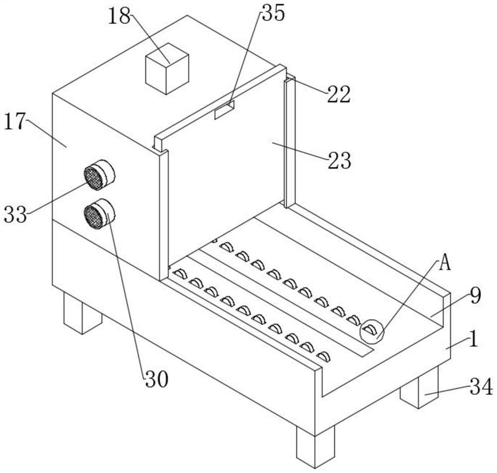
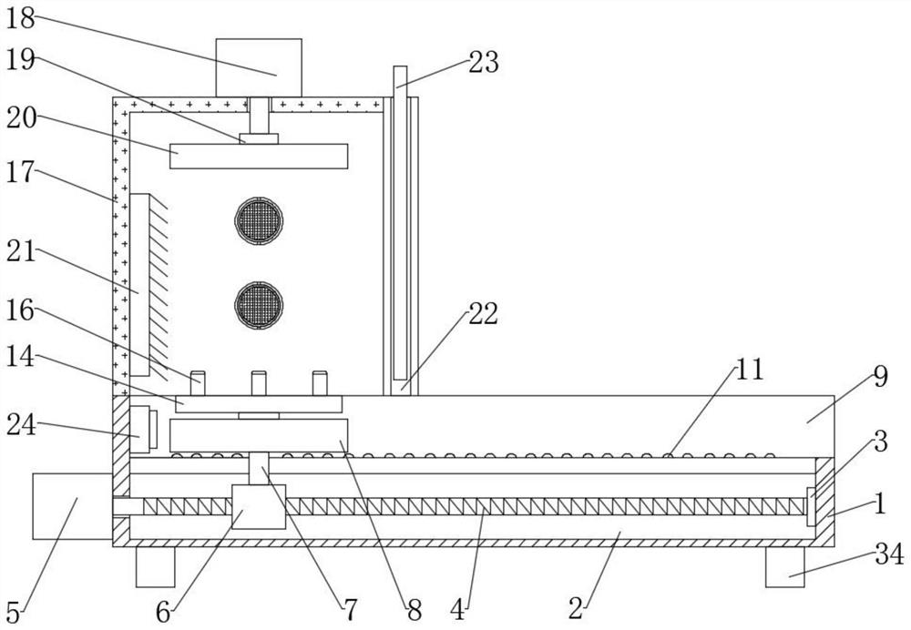
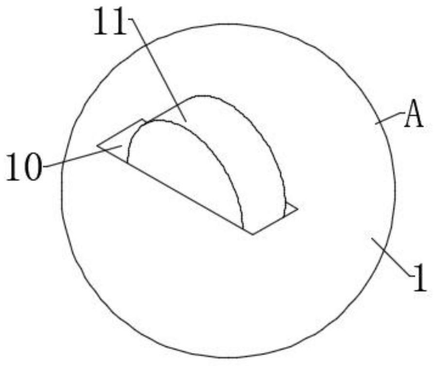
[0035] Such as Figure 1-7 As shown, the embodiment of the present invention provides an industrial robot cleaning equipment, including a base 1, the inside of the base 1 is provided with a movable groove 2, and the inner side of the movable groove 2 is fixedly connected with a first bearing seat 3, by setting the first bearing seat 3. It is convenient to rotate the threaded rod 4 with the inner wall of the movable groove 2. The inside of the first bearing seat 3 is fixedly connected with the threaded rod 4. The side surface of the base 1 is fixedly connected with the drive motor 5. The threaded rod 4 is controlled by the drive motor 5. Rotate, and control the threaded block 6 to drive the support rod 7, the slide plate 8, and the placement plate 14 to move, thereby controlling the industrial robot to move, avoiding manually pushing the industrial robot into the cleaning box 17, and the output shaft of the drive motor 5 extends to the movable slot 2 and is fixedly connected wi...

Embodiment 2

[0041] The difference between the present embodiment and the first embodiment is that an inclined block is set on the side surface of the base 1 and on the side opposite to the drive motor 5, and the inclined surface of the inclined block is provided with balls, which facilitates the industrial robot to pass through the inclined block. The shaped block slides onto the placement plate 14, avoiding manually lifting the industrial robot onto the placement plate 14, thereby reducing the labor force.

Embodiment 3

[0043] The difference between this embodiment and the first embodiment is that the driving motor 5 and the threaded rod 4 in the first embodiment can be replaced by hydraulic cylinders and telescopic rods, and the same can control the threaded block 6, the support rod 7, the slide plate 8, and place The plate 14 moves and moves the industrial robot into the cleaning tank 17 .


PUM


Abstract

The invention provides industrial robot cleaning equipment, and relates to the technical field of industrial robot cleaning. The industrial robot cleaning equipment comprises a base, wherein a movable groove is formed in the base; a first bearing seat is fixedly connected to the inner side of the movable groove; a threaded rod is fixedly connected to the interior of the first bearing seat; a driving motor is fixedly connected to the side surface of the base; an output shaft of the driving motor extends into the movable groove and is fixedly connected with the threaded rod; and the outer surface of the threaded rod is in threaded connection with a threaded block. The threaded rod is controlled to rotate through the driving motor, so that the threaded block is controlled to drive a supporting rod, a sliding plate and a placing plate to move, and an industrial robot is moved into a cleaning box; and rolling wheels are arranged for reducing friction between the sliding plate and a sliding groove, so that the sliding plate is moved more conveniently, the robot is prevented from being manually pushed into the cleaning box, and the working efficiency can be improved.

Description

technical field [0001] The invention relates to the technical field of industrial robot cleaning, in particular to an industrial robot cleaning equipment. Background technique [0002] With the rapid development of science and technology, the development of robots is gradually replacing workers in industrial production. A robot is a machine device that performs work automatically. It can accept human command, run pre-programmed programs, and act according to principles formulated with artificial intelligence technology. Its task is to assist or replace human work, such as production, construction, or dangerous work, but after the robot works for a long time, there will be a layer of dust on the surface that needs to be cleaned. [0003] However, in the prior art, the robot is cleaned by manually pushing the robot into the cleaning equipment. Since the robot itself is relatively difficult to push, it is troublesome to clean the robot every time, which seriously affects the w...

Claims


Application Information

Patent Timeline
Patent Type & Authority Applications(China)
IPC IPC(8): B08B5/04B08B1/02B08B13/00
CPCB08B1/002B08B1/02B08B5/043B08B13/00
Inventor 林闽南
Owner 泉州市智沃网络科技有限公司
Why Eureka
Try Eureka