Eureka AIR delivers breakthrough ideas for toughest innovation challenges, trusted by R&D personnel around the world.

Corrugated pipe

A corrugated pipe and pipe body technology, applied in pipe components, pipe heating/cooling, pipes/pipe joints/fittings, etc., to achieve the effect of strengthening sealing, solving pipe blockage, and preventing pipe falling off

Pending Publication Date: 2021-08-31
韦玉婷
View PDF6 Cites 0 Cited by
  • Summary
  • Abstract
  • Description
  • Claims
  • Application Information

AI Technical Summary

Problems solved by technology

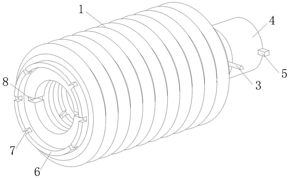
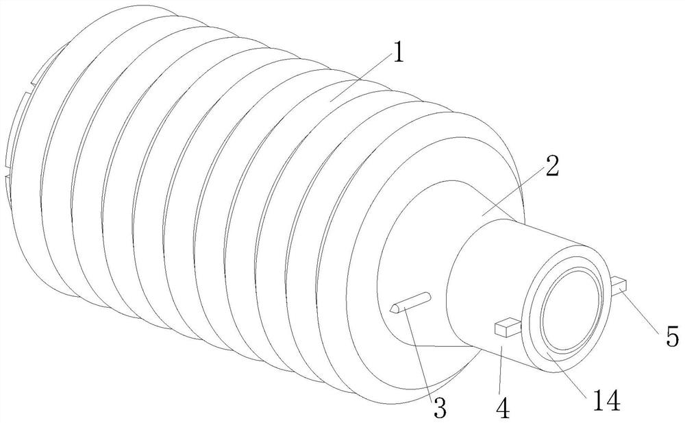
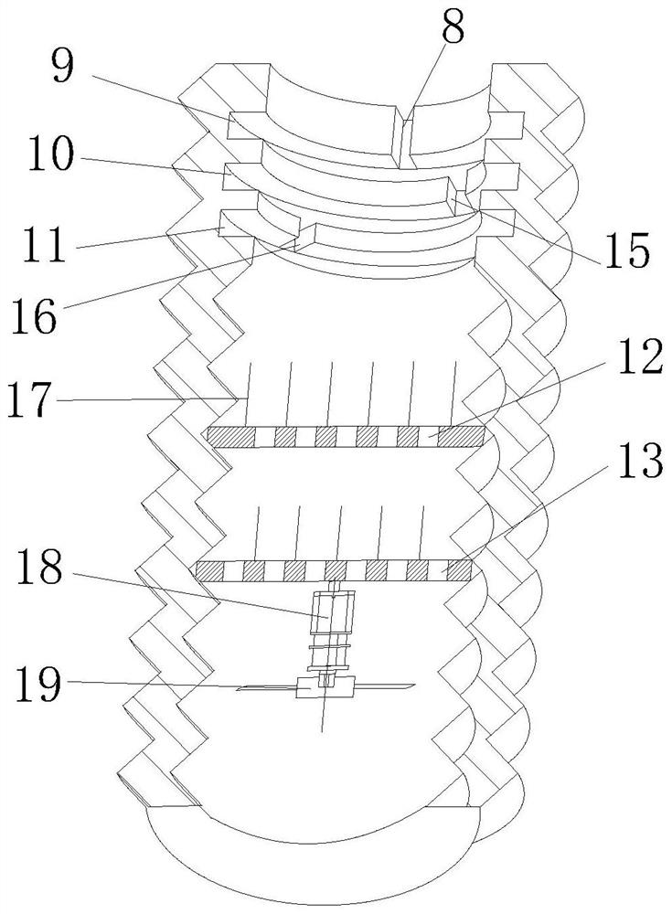
[0006] A corrugated pipe, comprising a pipe body, the right side of the pipe body is fixedly connected with a connector, the right side of the connector is fixedly connected with a joint, and the joint is facilitated by setting the connector; The surface is fixedly connected with a positioning pointer, and the left side of the pipe body is fixedly connected with a positioning plate. By setting the positioning pointer and the positioning plate, it is convenient to know the insertion position of the joint from the outside; the surface of the joint is fixedly connected with two sliders , the left side of the pipe body is provided with an inlet groove, the inner wall of the pipe body is respectively provided with a first-level arc-shaped groove, a second-level arc-shaped groove and a third-level arc-shaped groove, and the inner wall of the first-level arc-shaped groove is provided with a The inner wall of the second-level arc-shaped groove is provided with a second-level extension way, and the inlet groove is connected with the first-level arc-shaped groove. The first-level arc-shaped groove is convenient for the slider to slide in the groove, and is used to fix the slider to prevent the joint from falling off; the inner wall of the pipe is provided with a first-level filter block and a second-level filter block, and a steel filter block is fixedly connected above the first-level filter block. Needles, steel needles are fixedly connected above the secondary filter block, filter ports are provided on the end faces of the primary filter block and the secondary filter block, and the filter ports of the primary filter block and the secondary filter block are arranged alternately, and the secondary filter block The steel needle of the first-level filter block is aligned with the filter port of the first-level filter block to enhance the filtering effect of the pipe body; a sensor is fixedly connected between the position above the steel needle of the first-level filter block and the position below the third-level arc groove, and the A sensor is fixedly connected to the bottom of the secondary filter block, the sensor type is a liquid level sensor, a motor is fixedly connected to the bottom of the secondary filter block, a fan blade is fixedly connected to the bottom of the motor, and a battery is fixedly connected to the outer wall of the tube. The battery, steel needle, sensor and motor are all electrically connected to the controller. When the water flows through the pipe body, the fan blade and the motor are arranged to facilitate the rotation of the fan blade when the water flows through the pipe body, and the rotation of the fan blade drives the motor to rotate To store electricity for the battery; when the water flow does not flow through the pipe body, the sensor is used to detect whether there is water flowing above the first-stage filter block and below the second-stage filter block. The sensor detects that there is water flow above the first-stage filter block. When there is no water flow below the secondary filter block, it means that the pipe body is blocked; the controller controls the rotation of the fan blade to drive the secondary filter block to vibrate up and down to clear the filter port of the primary filter block to discharge the water; set the battery and steel needle for the steel needle to conduct electricity Heat and burn off the impurities on the surface, and at the same time, the rotation of the fan blade can discharge the smell generated when the steel needle heats and burns off the impurities from the pipe body; Delay the power off for a few minutes, and use the rotation of the fan blade to improve the cooling effect of the steel needle; thereby solving the problem that the existing corrugated pipe joint structure is relatively simple, generally using threaded connection, the joint cannot adjust the length of extension, and it is prone to leakage and pipe blockage Difficult to dredge, resulting in the problem that the smell cannot be discharged

Method used


Image

  • Corrugated pipe
  • Corrugated pipe
  • Corrugated pipe

Examples


Embodiment Construction

[0020] The following will clearly and completely describe the technical solutions in the embodiments of the present invention with reference to the accompanying drawings in the embodiments of the present invention. Obviously, the described embodiments are only some, not all, embodiments of the present invention. Based on the embodiments of the present invention, all other embodiments obtained by persons of ordinary skill in the art without making creative efforts belong to the protection scope of the present invention.

[0021] see Figure 1~5 , in an embodiment of the present invention, a corrugated pipe includes a pipe body 1, a connector 2 is fixedly connected to the right side of the pipe body 1, and a joint 4 is fixedly connected to the right side of the connector 2, and the joint is facilitated by setting the connector 2 4; the surface of the connector 2 is fixedly connected with a positioning pointer 3, and the left side of the tube body 1 is fixedly connected with a po...


PUM


Abstract

The invention relates to the technical field of corrugated pipes, in particular to a corrugated pipe. The corrugated pipe comprises a pipe body, the right side of the pipe body is fixedly connected with a connecting piece, the surface of the connecting piece is fixedly connected with a positioning pointer, the right side of the connecting piece is fixedly connected with a connector, the surface of the connector is fixedly connected with two sliding blocks, the left side of the pipe body is provided with an inlet groove, and a first-stage arc-shaped groove, a second-stage arc-shaped groove and a third-stage arc-shaped groove are formed in the inner wall of the pipe body correspondingly. In the corrugated pipe, the connecting piece is arranged so that stretching of the connector can be promoted conveniently; the first-stage arc-shaped groove, the second-stage arc-shaped groove and the third-stage arc-shaped groove are arranged so that the sliding blocks can slide in the grooves conveniently, meanwhile, the sliding blocks are fixed, and the connector is prevented from falling off; and by arranging the positioning pointer and a positioning disc, the stretching position of the connector can be conveniently known from the outside, and a storage battery and a steel needle are arranged for conducting and heating to dissolve impurities, so that the problems that an existing corrugated pipe connector is simple in structure, threaded connection is generally used, the stretching length of the connector cannot be adjusted, leakage is prone to occurring, and a pipe body is blocked are solved.

Description

technical field [0001] The invention relates to the technical field of bellows, in particular to a bellows. Background technique [0002] PVC pipe (UPVC pipe) rigid polyvinyl chloride pipe is made of polyvinyl chloride resin, stabilizer, lubricant, etc. and then extruded by hot pressing. It is the earliest plastic pipe that has been developed and applied. UPVC pipe has strong corrosion resistance , Easy to bond, low price, hard texture. [0003] However, the structure of the existing corrugated pipe joints is relatively simple. Generally, threaded connections are used, and the bellows needs to be rotated continuously for assembly, which is cumbersome. Moreover, the length of the joint cannot be adjusted, which is prone to leakage and internal blockage. Therefore, those skilled in the art provide a bellows to solve the problems raised in the background art above. Contents of the invention [0004] The purpose of the present invention is to provide a corrugated pipe, which...

Claims


Application Information

Patent Timeline
IPC IPC(8): F16L21/02F16L55/24F16L53/34
CPCF16L21/022F16L55/24F16L53/34
Inventor 韦玉婷周开
Owner 韦玉婷
Why Eureka
Eureka Blog
Learn More