Insulation pressing block and transformer

An insulating pressure block and insulating layer technology, which is applied in the field of transformers, can solve the problems of reducing the height of the insulating pressure block, the heavy size of the transformer, and the reduction of the iron core window.

Pending Publication Date: 2021-08-31
GUANGDONG CHANGKAI ELECTRIC CO LTD
View PDF0 Cites 0 Cited by
  • Summary
  • Abstract
  • Description
  • Claims
  • Application Information

AI Technical Summary

Problems solved by technology

[0004] Based on this, due to the structural characteristics of the traditional electrical ceramic insulation compact, the shed size cannot be designed too large according to the design requirements. If the creepage distance needs to be increased, the only way is to increase the number and height of the sheds. However, when the number and height of the sheds are increased, the whole transformer will be heavier and larger in size. An i...

Method used


Image

  • Insulation pressing block and transformer
  • Insulation pressing block and transformer
  • Insulation pressing block and transformer

Examples


Embodiment Construction

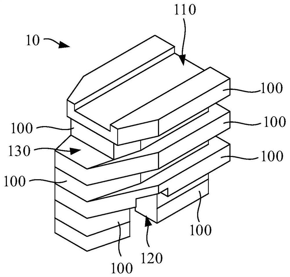
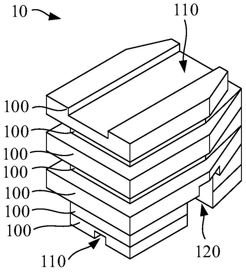
[0035] In order to make the above objects, features, and advantages of the present invention, the specific embodiments of the present invention will be described in detail below with reference to the accompanying drawings. Many specific details are set forth in the following description to fully understand the present invention. However, the present invention can be implemented in many other fails there are many otherwise described herein, and those skilled in the art may do similar improvements without departing from the connotation of the present invention, and thus the present invention is not limited by the specific embodiments disclosed below.

[0036] In the description of the invention, it is to be understood that the terms "center", "longitudinal", "horizontal", "length", "width", "thickness", "upper", "under", "front", " After "," left "," right "," vertical "," horizontal "," top "," bottom "," inside "," outside "," clockwise "," counterclock "," axial " , "Radial", "ci...


PUM


Abstract

The invention discloses an insulation pressing block and a transformer. The insulation pressing block comprises at least two insulating layers, wherein all the insulating layers are stacked in sequence, and one of the two adjacent insulating layers protrudes relative to the side edge of the other insulating layer. A traditional insulating pressing block is generally integrally formed by electrical ceramics. When the creepage distance of the insulation pressing block is increased by increasing the number of sheds of the insulation pressing block, the size and the weight of the transformer can be increased at the moment; and if the creepage distance of the insulation pressing block is increased by increasing the radian of the shed, the electrical ceramic insulation pressing block is prone to crack. Compared with a traditional insulation pressing block, the insulation pressing block comprises at least two insulating layers which are stacked in sequence, and one of the two adjacent insulating layers is arranged in a protruding mode relative to the side edge of the other insulating layer, thus when the creepage distance of the insulation pressing block needs to be adjusted, only the protruding length of one of the two adjacent insulating layers relative to the other insulating layer needs to be adjusted.

Description

Technical field [0001] The present invention relates to the technical field of the transformer, more particularly to a compact and insulation transformer. Background technique [0002] The three-dimensional iron core dry transformer is completely symmetrical due to its three-phase magnetic circuit of the core, with a small magnetic resistance, the excitation current, and the low-cost loss, and the economic benefits are very significant and therefore extensive applications. The upper and lower end surfaces of the dry transformer coil are typically mounted to press the fixing coil, and the currently common dry transformer coils are mostly electrical ceramics. [0003] However, the conventional electrical insulating ceramic compact formula, due to the structural characteristics of electroceramics, the size can not shed much design according to design requirements, increase the creepage distance if desired, can be achieved by increasing the number and height of the shed, However, whe...

Claims


Application Information

Patent Timeline
IPC IPC(8): H01F27/32H01B17/56
CPCH01B17/56H01F27/32
Inventor 许凯旋方文杰谭卫锋李万欢周宇成许权安张启立张学明李飞王华明
Owner GUANGDONG CHANGKAI ELECTRIC CO LTD
Why Eureka
Try Eureka