
Watercraft

A raft body and flow channel technology, applied in the field of rafts, can solve the problems of inconvenience, large flow resistance, and inability to use

Pending Publication Date: 2021-08-31
卡购技术股份有限公司
View PDF3 Cites 0 Cited by
  • Summary
  • Abstract
  • Description
  • Claims
  • Application Information

AI Technical Summary

Problems solved by technology

This known raft is relatively bulky in construction and is therefore not portable
Especially when driving in water where small curve radii should be driven it is not possible to use said raft
In addition, the raft has a high structural height such that it offers a relatively large resistance to flow

Method used


Image

  • Watercraft
  • Watercraft
  • Watercraft

Examples


Embodiment Construction

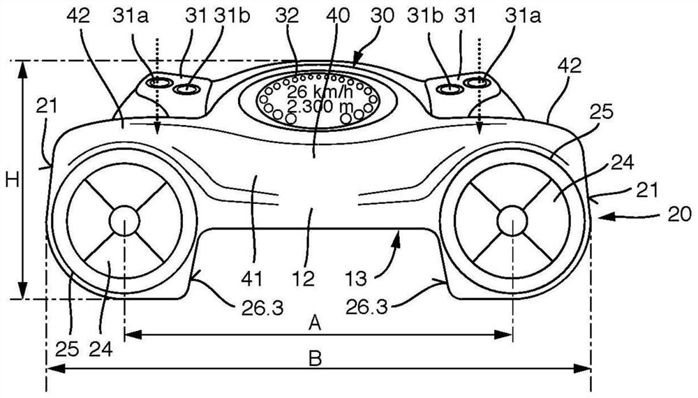
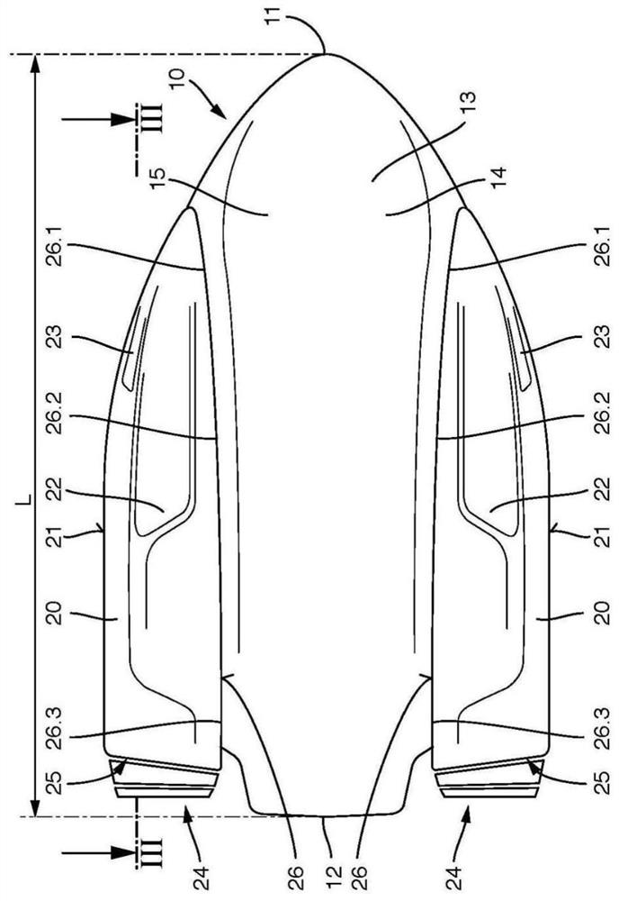
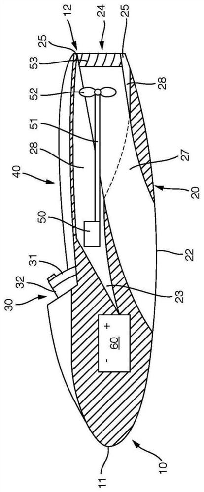
[0031] figure 1 and figure 2 A raft is shown having a hull 10 with a bow 11 and a tail 12 . A cockpit 30 with a display 32 is arranged in the region of the nose 11 . Specific operating parameters of the raft can be displayed via the display 32 . For example, the state of charge of the power source 60 , diving depth or speed may be displayed via the display 32 .

[0032] A handle 31 is provided on both sides of the handle 31 at the cockpit 30 . The user can grip the raft at the handle. The handle 31 may have control elements 31A, 31B.

[0033] The bearing surface 40 is connected to the cockpit 30 in the direction of the tail section 12 . The user can partially rest on the support surface 40 , for example by supporting an arm and / or a partial region of his upper body. Preferably, as figure 1 As shown, the bearing surface 40 is provided with a groove-shaped deepening in the central region. However, it is also conceivable that instead of a deepening, an outwardly arched mi...


PUM


Abstract

The invention relates to a watercraft, in particular a swimming and / or diving aid, comprising a hull (10) which has a stern (12) and a bow (11), wherein: two flow channels (27) are provided in the hull (10) or on the hull (10) and run from a water inlet (22) to a water outlet (24); a water acceleration device (52), in particular a propeller or a water screw, is located in each of the two flow channels (27); each water acceleration device (52) is driven by a motor (50); handles (31), on to which a user can hold, are located in the central region between the bow (11) and the stern (12) or in the bow region; a support surface (40), on at least part of which a user can rest, is provided adjacent to the handles (31) in the direction towards the stern (12); and two spaced-apart bulged portions, which extend in the longitudinal direction of the hull (10) and between which at least one water planing surface (14, 15) is located, are provided on the underside of the hull (10). In order to be able to achieve low flow resistance in such a watercraft with a compact structure, according to the invention the flow channels (27) extend, at least in certain areas, in the region of the bulged portions.

Description

technical field [0001] The invention relates to a raft, in particular a swimming and / or diving aid, having a raft body with a tail and a bow, wherein two flow channels are provided in or at the raft body, said A flow channel extends from the water inlet to the water outlet, wherein in each of the two said flow channels there is provided a water acceleration device, in particular a propeller or a water pushing propeller, wherein each water acceleration device is driven by a motor, wherein The handle is arranged in the middle region between the head and the tail or is arranged in the head region, the user can grasp at the handle, wherein in the direction of the tail, the handle is connected to a support surface, and the user can at least partially support (aufliegen ) on said support surface, and wherein two projections spaced apart from each other and extending in the longitudinal direction of the raft are provided on the underside of the raft, between which at least one water-...

Claims


Application Information

Patent Timeline
Patent Type & Authority Applications(China)
IPC IPC(8): B63B32/10B63B34/10B63B35/12B63C11/46B63H11/00
CPCB63B34/10B63C11/46B63B35/12B63B32/10B63H11/00B63H21/17B63H2011/081B63H2011/008B63H2021/216B63H11/08
Inventor H-P·瓦尔普吉斯
Owner 卡购技术股份有限公司
Learn More