
Three-shaft shredding machine

A shredder and knife shaft technology, which is applied in grain processing and other directions, can solve the problems of high cost, low relative efficiency, and easily damaged screens, etc., and achieve the effects of low use cost, high shredding efficiency, and cost reduction

Pending Publication Date: 2021-09-03
昆山格锐精密机械有限公司
View PDF0 Cites 0 Cited by
  • Summary
  • Abstract
  • Description
  • Claims
  • Application Information

AI Technical Summary

Problems solved by technology

[0002] Existing three-shaft shredders generally have a screen through which the size of the material is controlled. When the material does not reach the discharge size of the screen, it will be repeatedly crushed in the shredding cavity, so the relative efficiency is low; When the size and strength of the material to be crushed is large, the impact on the screen is greater, so it is easy to damage the screen, or the blades often reverse; the gap between the blades is small, and the tearing is completed by side shearing. Crushing work, when a certain degree of wear occurs on the side of the blade, the blade will quickly fail, and it needs to be replaced with a new blade to continue to use, and the cost is high

Method used


Image

  • Three-shaft shredding machine
  • Three-shaft shredding machine
  • Three-shaft shredding machine

Examples


Embodiment Construction

[0024] In order to make the above objects, features and advantages of the present invention more comprehensible, specific implementations of the present invention will be described in detail below in conjunction with the accompanying drawings. In the following description, numerous specific details are set forth in order to provide a thorough understanding of the present invention. However, the present invention can be implemented in many other ways different from those described here, and those skilled in the art can make similar improvements without departing from the connotation of the present invention, so the present invention is not limited by the specific embodiments disclosed below.

[0025] In describing the present invention, it should be understood that the terms "center", "longitudinal", "transverse", "length", "width", "thickness", "upper", "lower", "front", " Back", "Left", "Right", "Vertical", "Horizontal", "Top", "Bottom", "Inner", "Outer", "Clockwise", "Counte...


PUM


Abstract

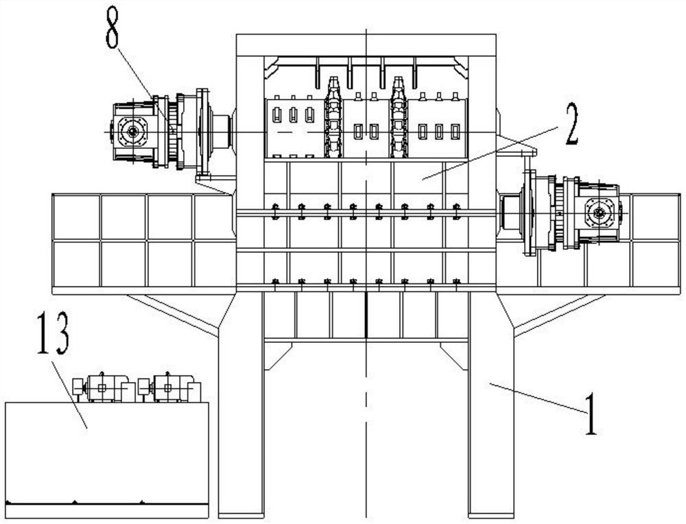
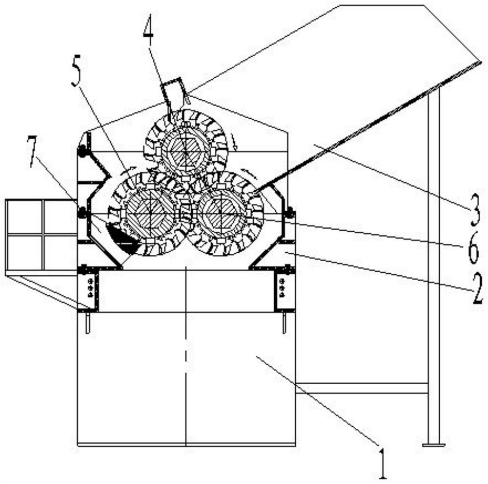
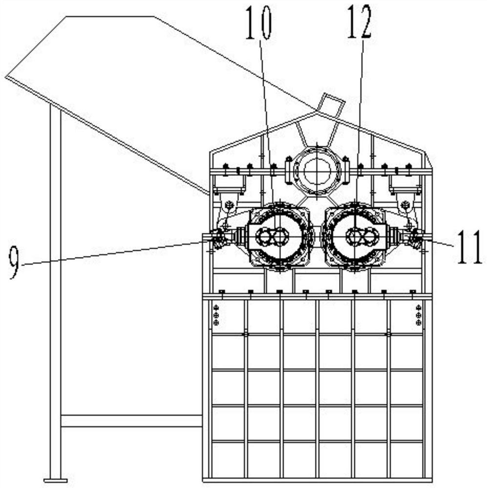
The invention discloses a three-shaft shredding machine which comprises a box body, a first cutter shaft, a second cutter shaft and a third cutter shaft; a shredding cavity is formed in the box body, and a feeding opening communicating with the shredding cavity is formed in the top of the box body; the first cutter shaft is rotatably arranged in the shredding cavity of the box body around a first axis, and a first blade is arranged on the first cutter shaft; the second cutter shaft and the third cutter shaft are rotatably arranged in the shredding cavity of the box body around a second axis and a third axis correspondingly, the second axis and the third axis are located below the two sides of the first axis respectively, the second axis and the third axis are parallel to the first axis respectively, and a second blade and a third blade are arranged on the second cutter shaft and the third cutter shaft correspondingly; and the second blade and the third blade are respectively staggered and matched with the first blade, and the second blade and the third blade are mutually staggered and matched with each other. According to the three-shaft shredding machine, materials are shredded three times after entering the shredding cavity from the feeding opening, and therefore the shredding efficiency is higher compared with other three-shaft shredding machines.

Description

technical field [0001] The invention relates to the technical field of material shredding, in particular to a three-shaft shredder. Background technique [0002] Existing three-shaft shredders generally have a screen through which the size of the material is controlled. When the material does not reach the discharge size of the screen, it will be repeatedly crushed in the shredding cavity, so the relative efficiency is low; When the size and strength of the material to be crushed is large, the impact on the screen is greater, so it is easy to damage the screen, or the blades often reverse; the gap between the blades is small, and the tearing is completed by side shearing. For crushing work, when a certain degree of wear occurs on the side of the blade, the blade will fail quickly, and it needs to be replaced with a new blade to continue to use, and the cost is relatively high. Contents of the invention [0003] The object of the present invention is to provide a three-sha...

Claims


Application Information

Patent Timeline
IPC IPC(8): B02C18/14B02C18/18B02C18/24B02C18/22B02C18/16
CPCB02C18/142B02C18/18B02C18/24B02C18/2225B02C18/16
Inventor 葛平张干孝
Owner 昆山格锐精密机械有限公司
Learn More