Door stopper and door seal unsealing groove demolding mechanism
A demoulding mechanism and door suction technology, which is applied in the field of refrigerator processing auxiliary equipment, can solve the problems of low efficiency and manpower consumption, and achieve the effects of reducing damage rate, improving efficiency, and uniform force
- Summary
- Abstract
- Description
- Claims
- Application Information
AI Technical Summary
Problems solved by technology
Method used
Image
Examples
Embodiment 1
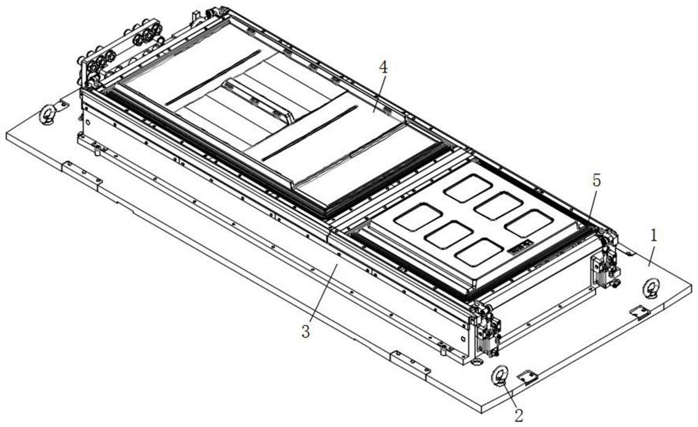
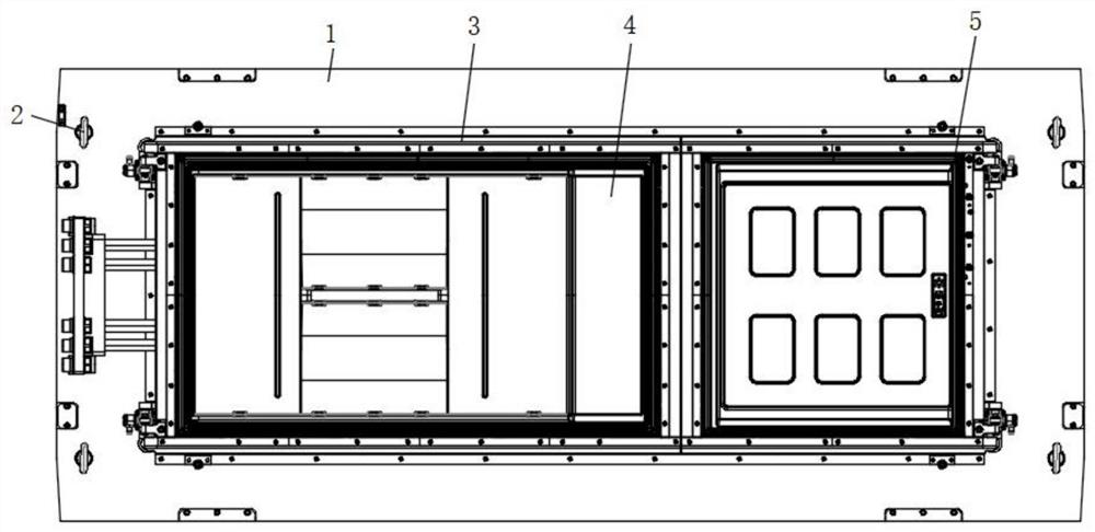
[0032] refer to Figure 1-9 , a door suction door seal release groove demoulding mechanism, including a bottom plate 1, the top surface of the bottom plate 1 is fixed with lifting lugs 2, the middle part of the top surface of the bottom plate 1 is fixed with an outer mold body 3, and an inner mold body is arranged inside the outer mold body 3 4. A demoulding assembly 5 is provided at the junction of the outer mold body 3 and the inner mold body 4. The demoulding assembly 5 includes a mounting bar 511, which is fixed on the inner wall of the outer mold body 3, and the inner mold body 4 is connected to the outer mold body. A door seal inner part 512 and a door seal outer part 513 are respectively fixed at the junction of the mold body 3, and the demoulding assembly 5 is used for the demoulding of the door seal groove structure of the refrigerator freezer door liner.
Embodiment 2
[0034] Such as Figure 1-6 As shown, this embodiment is basically the same as Embodiment 1. Preferably, the upper end of the outer part 513 of the door seal is close to the side of the outer mold body 3 and a retaining strip 514 is installed. Both ends are equipped with hinges 515, and guide blocks 516 are installed on both sides of the intersection of the inner part of the door seal 512 and the outer part of the door seal 513, and the bottom ends of the inner part of the door seal 512 and the outer part of the door seal 513 are also provided with push rods 517, The lower end of the ejector rod 517 extends to the outside of the inner mold body 4 , and a waterway connection pipe 518 is arranged on one side of the ejector rod 517 , and the upper end of the waterway connection pipe 518 is connected to the bottom surface of the inner mold body 4 through.
[0035] The demoulding assembly 5 includes a retaining bar 514 disposed directly above the mounting bar 511 .
[0036] There a...
Embodiment 3
[0039] Such as Figure 1-4 As shown in 7-9, this embodiment is basically the same as Embodiment 1. Preferably, preferably, the bottom end of the inner part 512 of the door seal and the outer part 513 of the door seal are provided with a limit strip 521, and the lower end of the inner part of the door seal 512 is close to the inner A guide column 522 is installed on one side of the mold body 4, and a connecting piece 523 is fixedly connected between the door seal outer part 513 and the installation bar 511. A pressing plate 525 is also fixed, and the outer part 513 of the door seal has a guide piece 526 near the side of the outer mold body 3 in Erhai, Anhui Province.
[0040] The limiting strips 521 are fixed through the bottom surface of the inner mold body 4 , and there are multiple limiting strips 521 evenly distributed on the lower side of the inner part 512 of the door seal.
[0041]A plurality of guide posts 522 are provided and evenly distributed on the side of the lowe...
PUM
 Abstract
Description
Claims
Application Information
 - R&D
- Intellectual Property
- Life Sciences
- Materials
- Tech Scout
- Unparalleled Data Quality
- Higher Quality Content
- 60% Fewer Hallucinations
Browse by: Latest US Patents, China's latest patents, Technical Efficacy Thesaurus, Application Domain, Technology Topic, Popular Technical Reports.
© 2025 PatSnap. All rights reserved.Legal|Privacy policy|Modern Slavery Act Transparency Statement|Sitemap|About US| Contact US: help@patsnap.com


