
Automatic roll changing mechanism of high-speed film blowing machine

A film blowing machine, automatic technology, applied in the field of automatic roll changing mechanism of high-speed film blowing machine, can solve the problems of large volume and weight, danger, waste of operating time, etc.

Active Publication Date: 2021-09-03
浙江松山机械有限公司
View PDF6 Cites 0 Cited by
  • Summary
  • Abstract
  • Description
  • Claims
  • Application Information

AI Technical Summary

Problems solved by technology

[0002] With the development of industrial technology, modern plastic film manufacturing technology has become more and more perfect. Due to the relatively large demand for plastic film, the current plastic film is mass-produced in factories. The raw material of plastic film is short fiber particles. These short fiber particles are solid, so when feeding the film blowing machine, the staff needs to transport the material frame containing the short fiber to the feed port of the device, and the volume of the feed mine containing the short fiber The weight and weight are relatively large, so it is more troublesome for the staff to transport the material frame, and it is easy to hurt the staff, which is dangerous to a certain extent;
[0003] When the rewinding roller of the plastic film is full of materials, the staff still needs to manually remove the material roller and replace it with a new material roller for rewinding, so for mass production needs, the process of replacing the material roller will waste A lot of operating time reduces work efficiency
[0004] Just like the film blowing machine announced in 201810402474.7, the film blowing machine equipment needs manual feeding, and the equipment cannot automatically replace the material roller, which will waste a lot of labor and increase labor costs

Method used


Image

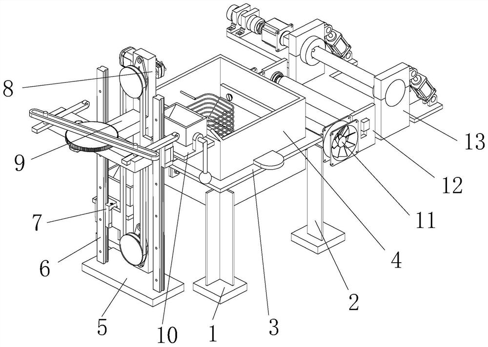
  • Automatic roll changing mechanism of high-speed film blowing machine
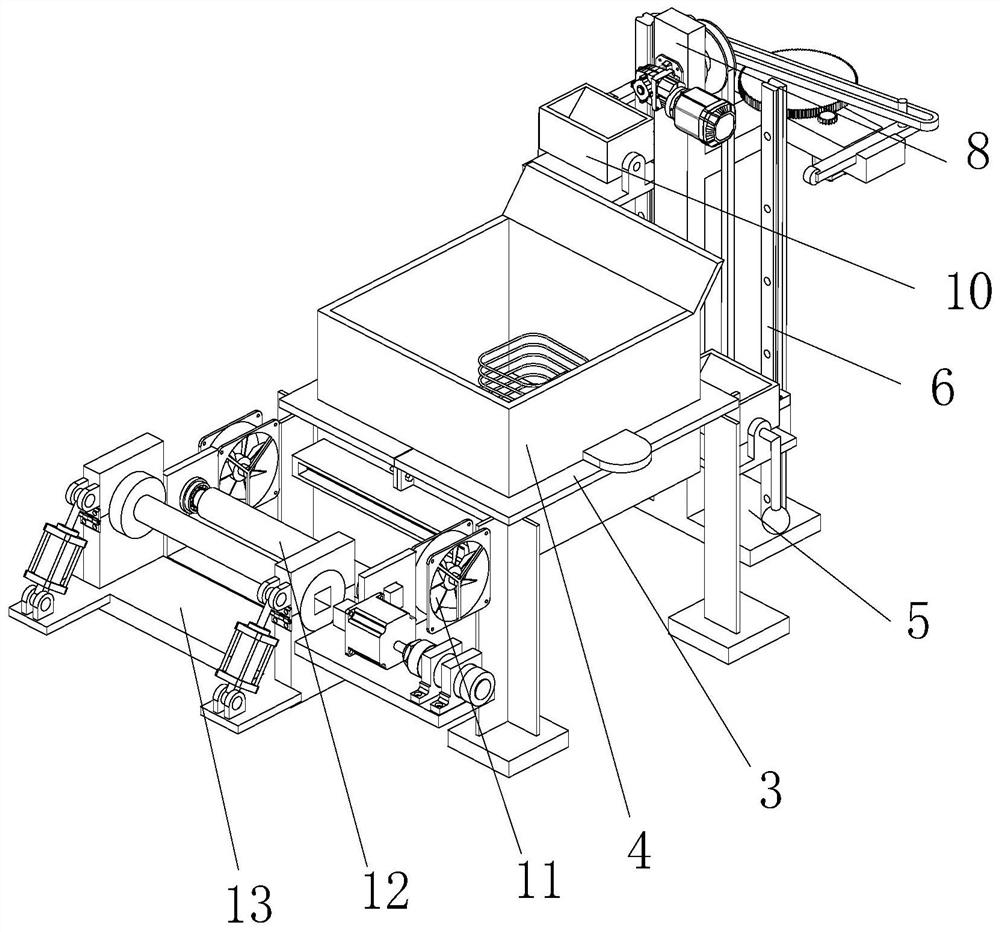
  • Automatic roll changing mechanism of high-speed film blowing machine
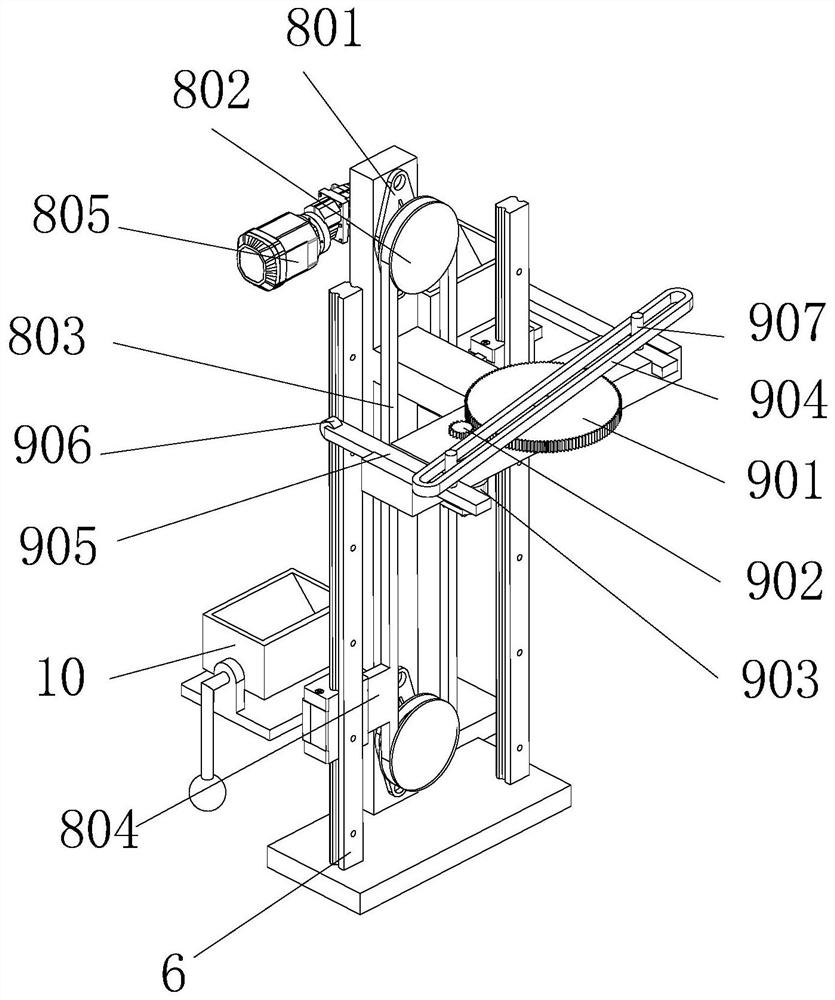
  • Automatic roll changing mechanism of high-speed film blowing machine

Examples


Embodiment Construction

[0029] In order to make the object, technical solution and advantages of the present invention clearer, the present invention will be further described in detail below in conjunction with the accompanying drawings and embodiments. It should be understood that the specific embodiments described here are only used to explain the present invention, not to limit the present invention.

[0030] In describing the present invention, it should be understood that the terms "longitudinal", "transverse", "upper", "lower", "front", "rear", "left", "right", "vertical", The orientations or positional relationships indicated by "horizontal", "top", "bottom", "inner", "outer", etc. are based on the orientations or positional relationships shown in the drawings, and are only for the convenience of describing the present invention, rather than indicating or It should not be construed as limiting the invention by implying that a referenced device or element must have a particular orientation, be...


PUM


Abstract

The invention discloses an automatic roll changing mechanism of a high-speed film blowing machine, and belongs to the field of film blowing machines. The automatic roll changing mechanism comprises four bases which are independently and fixedly mounted, reinforcing metal plates are arranged at the top ends of the bases, carrying turnups are arranged on the two sides of a heating frame, the carrying turnups are attached to the top surface of a detachable top frame, and a spiral wire is arranged on the inner side of the heating frame. The two ends of the spiral wire are connected with the side wall of the heating frame, the two ends of the spiral wire are connected with alternating current, metal fins are arranged on the inner side of the spiral wire, an additionally-installed piece is arranged on the inner wall of the heating frame and connected with the inner wall of the heating frame through screws, and two liquid leakage holes are formed in the additionally-installed piece. A discharging channel is arranged at the bottom end of the heating frame, the end of the additionally-installed piece penetrates through the discharging channel, a certain gap is reserved between the bottom end of the additionally-installed piece and the discharging channel, and a slope plate is arranged at the top end of the heating frame. When viscous materials pass through the discharging channel, a double-layer film can be formed.

Description

technical field [0001] The invention relates to the field of film blowing machines, in particular to an automatic roll changing mechanism of a high-speed film blowing machine. Background technique [0002] With the development of industrial technology, modern plastic film manufacturing technology has become more and more perfect. Due to the relatively large demand for plastic film, the current plastic film is mass-produced in factories. The raw material of plastic film is short fiber particles. These short fiber particles are solid, so when feeding the film blowing machine, the staff needs to transport the material frame containing the short fiber to the feed port of the device, and the volume of the feed mine containing the short fiber The weight and weight are relatively large, so it is more troublesome for the staff to transport the material frame, and it is easy to hurt the staff, which is dangerous to a certain extent; [0003] When the rewinding roller of the plastic ...

Claims


Application Information

Patent Timeline
Patent Type & Authority Applications(China)
IPC IPC(8): B29C55/28B29C48/285B29C48/80B29C48/28B29C48/10
CPCB29C55/28B29C48/285B29C48/802B29C48/28B29C48/10
Inventor 张小国
Owner 浙江松山机械有限公司
Learn More