Surface embossing device for electronic product production

An electronic product and surface pressing technology, which is applied in decorative arts, painting tools, embossed ornaments, etc., can solve the problems of difficult replacement of embossed patterns, low stability, and easy deviation of embossed positions, so as to increase stability and improve The effect of work efficiency

Active Publication Date: 2021-09-03
南通迪贝德精密电子有限公司
View PDF11 Cites 0 Cited by
  • Summary
  • Abstract
  • Description
  • Claims
  • Application Information

AI Technical Summary

Problems solved by technology

[0005] In order to overcome the shortcomings of the existing embossing equipment for electronic products, which can only be embossed one by one, which is difficult to meet the needs of the current market, the stability of the embossing process is low, the embossing position is easy to deviate, and the embossing pattern is difficult to replace. The technical problem to be solved is: to provide a surface embossing device for the production of electronic products that has intermittent feeding and can change different patterns

Method used


Image

  • Surface embossing device for electronic product production
  • Surface embossing device for electronic product production
  • Surface embossing device for electronic product production

Examples


Embodiment 1

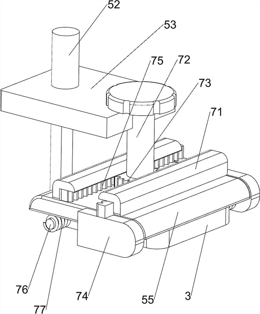
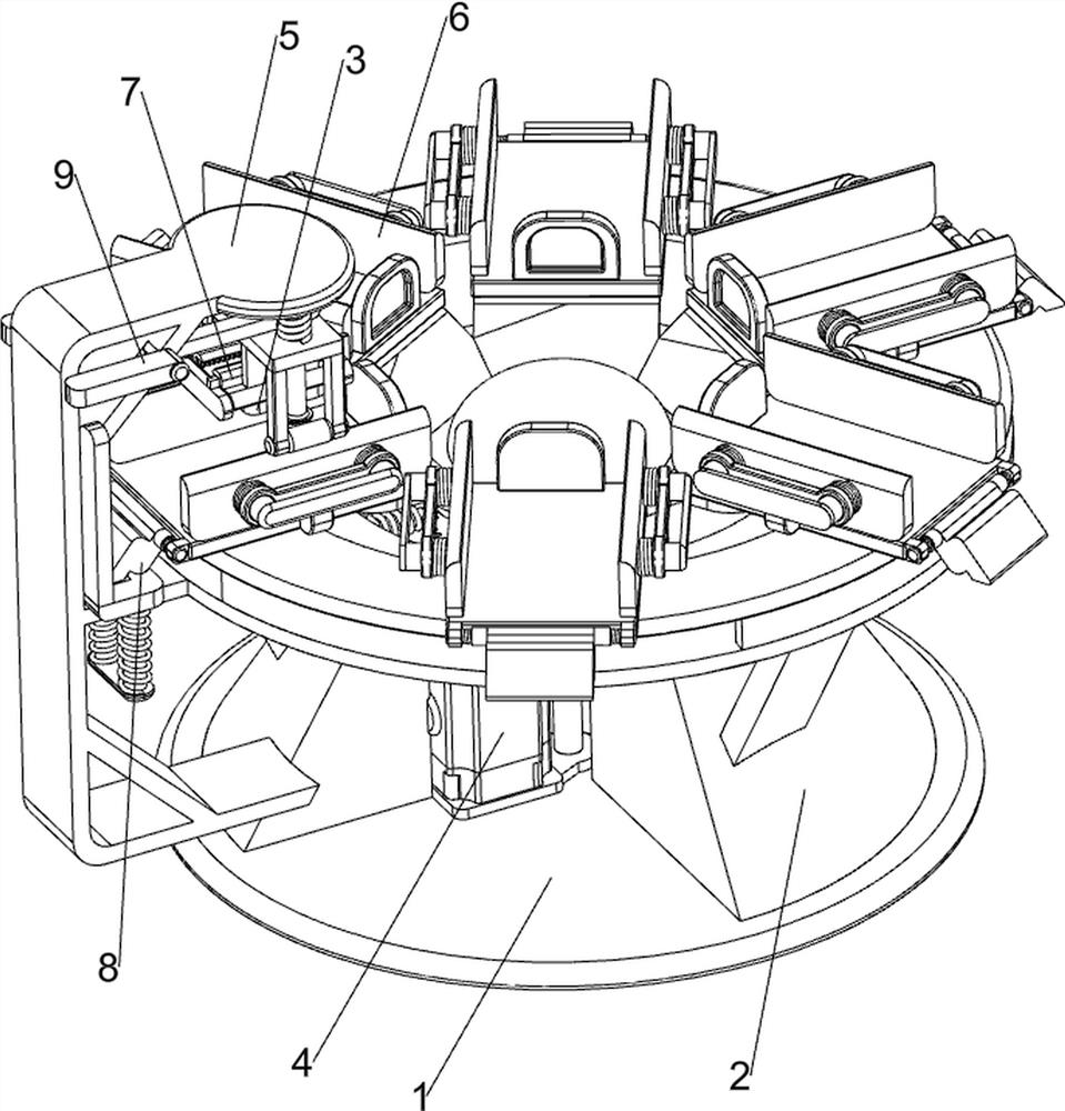
[0038] A surface embossing device for the production of electronic products, such as Figure 1-Figure 8 As shown, it includes a chassis 1, a supporting frame 2, an embossing block 3, a rotating mechanism 4 and an embossing mechanism 5. The top of the chassis 1 is provided with a supporting frame 2, and the inner side of the supporting frame 2 is provided with a rotating mechanism 4. The left side of the supporting frame 2 An embossing mechanism 5 is provided, and an embossing block 3 is arranged on the embossing mechanism 5, and the left and right sides of the embossing block 3 are symmetrically provided with grooves.

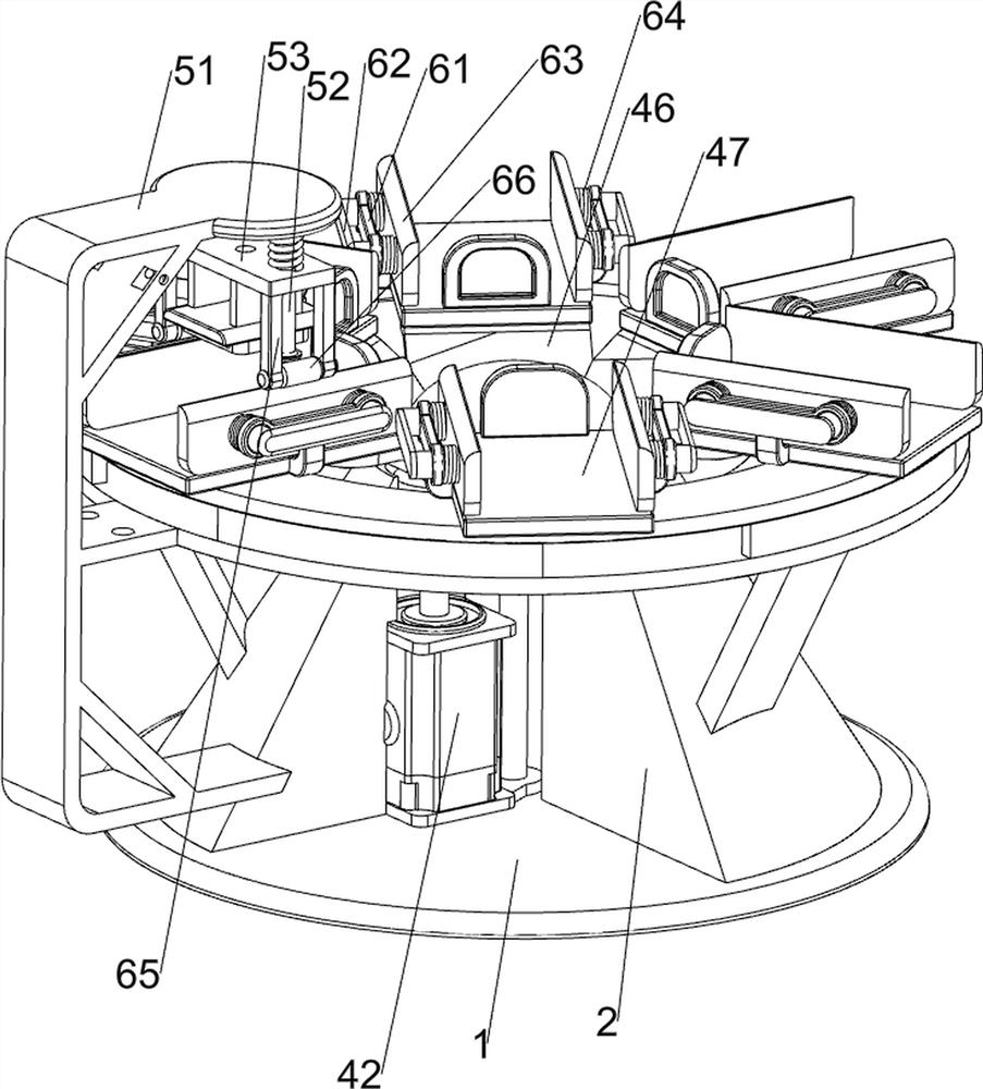
[0039]The rotating mechanism 4 includes a first limiting block 41, a reduction motor 42, a missing gear 43, a first rotating shaft 44, a first gear 45, a connecting plate 46 and a placement plate 47, and a first limiting block is arranged in the middle of the lower side of the support frame 2. Bit block 41, first limit block 41 top is provided with deceleration...

Embodiment 2

[0043] On the basis of Example 1, such as Figure 9-Figure 18 As shown, the clamping assembly 6 is also included, and the clamping assembly 6 includes a guide block 61, a push rod 62, a clamping plate 63, a second spring 64, a connecting rod 65 and a roller 66, and the placing plate 47 is provided with two A guide block 61, the inner upper side of the guide block 61 is all slidingly provided with a push rod 62, and the inside of the push rod 62 is provided with a clamping plate 63, and the clamping plate 63 is located on both sides of the top of the placement plate 47, and the clamping plate 63 is connected to the top of the plate 47. The second spring 64 is arranged symmetrically between the guide blocks 61 , the front and rear sides of the bottom of the slide plate 53 are provided with connecting rods 65 , and the lower side of the connecting plate 46 is rotatably provided with rollers 66 , and the rollers 66 cooperate with the clamping plate 63 .

[0044] When the slide pla...


PUM


Abstract

The invention relates to an embossing device, in particular to a surface embossing device for electronic product production. The technical problem to be solved is how to provide the surface embossing device for electronic product production capable of achieving intermittent feeding and replacement of different patterns. According to the technical scheme, the surface embossing device for electronic product production comprises a base plate, a supporting frame fixedly connected to the top of the base plate, a rotating mechanism mounted on the inner side of the supporting frame, an embossing mechanism arranged on one side of the supporting frame and an embossing block connected to the embossing mechanism, and grooves are symmetrically formed in the two sides of the embossing block. When rolling wheels move downwards to be in contact with clamping plates, the clamping plates and push rods are driven to move inwards, the clamping plates clamp electronic products, the electronic products can be stably embossed, and the stability of the electronic products is improved.

Description

technical field [0001] The invention relates to an embossing device, in particular to a surface embossing device for electronic product production. Background technique [0002] Embossing means that under the action of pressure, the pattern formed on the composite material is pressed on a certain item. Due to the rise of electronic products, the embossing on the surface of electronic products is also developing continuously, and emerges in endlessly. [0003] Embossing on the surface of electronic products can improve the aesthetic effect and is loved by many people. Nowadays, in the existing electronic product embossing equipment, embossing can only be carried out one by one, and the product needs to be embossed manually, which affects work efficiency and is difficult to meet The current market demand, and the low stability in the embossing process, the embossed position is easy to deviate, and the embossed pattern is difficult to replace, resulting in problems such as a re...

Claims


Application Information

Patent Timeline
Patent Type & Authority Applications(China)
IPC IPC(8): B44B5/00B44B5/02
CPCB44B5/0023B44B5/0061B44B5/02B44B5/022B44B5/026B44B2700/12Y02P70/10
Inventor 彭妍
Owner 南通迪贝德精密电子有限公司
Why Eureka
Try Eureka