Hydrogen fuel cell auxiliary power supply system and electromagnetic compatibility rectification circuit thereof
A fuel cell and power supply system technology, which is applied in battery/battery traction, current collectors, power management, etc., can solve problems such as low anti-interference and poor electromagnetic compatibility, and achieve poor electromagnetic compatibility, prolong service life, shorten The effect of EMC design optimization time
- Summary
- Abstract
- Description
- Claims
- Application Information
AI Technical Summary
Problems solved by technology
Method used
Image

Examples
Embodiment 1
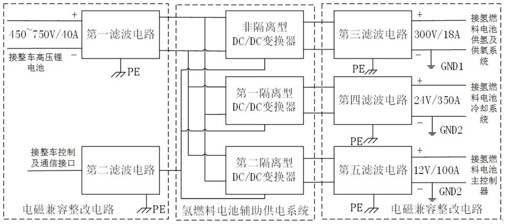
[0036] Such as figure 1 As shown, the present invention provides an auxiliary power supply system for a hydrogen fuel cell. The hydrogen fuel cell includes a hydrogen and oxygen supply system, a cooling system, a main controller and a PE interface of the casing.
[0037] The hydrogen fuel cell auxiliary power supply system includes a battery auxiliary power supply circuit and an electromagnetic compatibility rectification circuit; the battery auxiliary power supply circuit includes a non-isolated DC / DC converter, a first isolated DC / DC converter and a second isolated DC / DC converter; The electromagnetic compatibility correction circuit includes a first filter circuit, a second filter circuit, a third filter circuit, a fourth filter circuit and a fifth filter circuit.
[0038] The input end of the first filter circuit is connected to the high-voltage lithium battery of the vehicle, which filters the ripple in the output voltage of the high-voltage lithium battery of the vehicle...
Embodiment 2
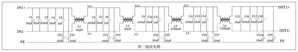
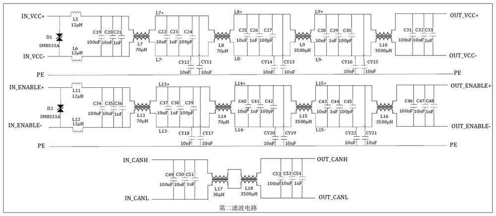
[0044] Such as figure 2 and 3 As shown, in the electromagnetic compatibility rectification circuit of Embodiment 1, capacitors C110μ, C30μ, C20μ, C100n, C10n, C1n, and C100p are preferably farad capacitors, and capacitors C110μ=110μF, C30μ=30μF, C20μ=20μF, C100n=100nF, C10n =10nF, C1n=1nF, C100p=100pF. The capacitor CY is preferably a Y capacitor, and CY1 to CY48 are all Y capacitors CY=10nF.
[0045] Inductors L1, L2, L7, L8, L13, L14, L17, L19 and L20 are preferably nickel-zinc magnetic ring common-mode inductors. L1=L2=L17=L19=L20=30 μH, L7=L8=L13=L14=70 μH.
[0046] Inductors L3, L4, L9, L10, L15, L16, L18, L21, L22, L23, L24, L25, L26, L27 and L28 are preferably amorphous magnetic ring common mode inductors. L3=L4=L21=L22=2300 μH; L9=L10=L15=L16=L18=3500 μH; L23=L24=L25=L26=L27=L28=70 μH.
[0047] The inductor LC is preferably a differential mode inductor, L5, L6, L11, and L12 are LC=12μH, and the diodes D1 and D2 are preferably transient voltage suppression diodes ...
PUM
 Abstract
Description
Claims
Application Information
 - R&D Engineer
- R&D Manager
- IP Professional
- Industry Leading Data Capabilities
- Powerful AI technology
- Patent DNA Extraction
Browse by: Latest US Patents, China's latest patents, Technical Efficacy Thesaurus, Application Domain, Technology Topic.
© 2024 PatSnap. All rights reserved.Legal|Privacy policy|Modern Slavery Act Transparency Statement|Sitemap