Anti-stall double-layer pump inlet structure

A double-layer, inlet-side technology, used in pumps, pump components, non-variable-capacity pumps, etc., can solve the problems of internal flow disturbance, large vibration and noise, and increased hydraulic loss, and achieves the goal of suppressing non-uniform flow and improving Anti-stall performance, uniform and stable water inflow

A double-layer, inlet-side technology, used in pumps, pump components, non-variable-capacity pumps, etc., can solve the problems of internal flow disturbance, large vibration and noise, and increased hydraulic loss, and achieves the goal of suppressing non-uniform flow and improving Anti-stall performance, uniform and stable water inflow

CN113339318AActive Publication Date: 2021-09-03JIANGSU UNIV

Image

  • Anti-stall double-layer pump inlet structure
  • Anti-stall double-layer pump inlet structure
  • Anti-stall double-layer pump inlet structure

Examples


Embodiment Construction

[0031] Embodiments of the present invention are described in detail below, and examples of the illustrated embodiments are illustrated in the drawings, wherein like or similar reference numerals designate the same or similar elements or elements having the same or similar functions throughout. The embodiments described below by referring to the figures are exemplary and are intended to explain the present invention and should not be construed as limiting the present invention.

[0032] 1. Structure Description

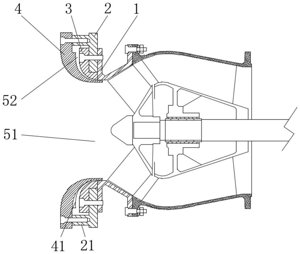
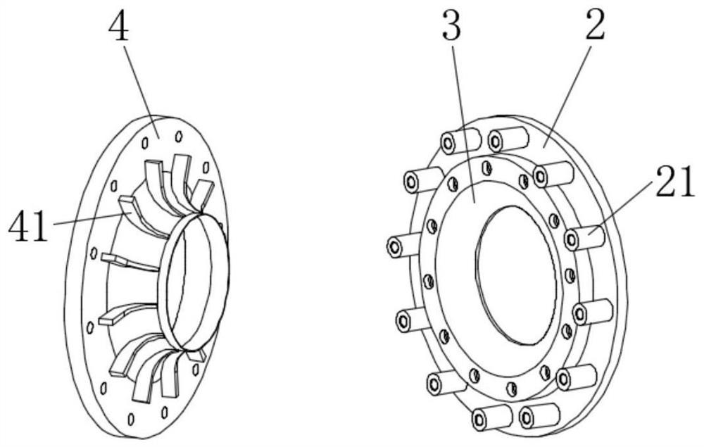
[0033] Such as figure 1 and figure 2 In the anti-stall double-layer pump inlet structure shown, the end of the pump casing 1 located at the pump inlet is connected with a mounting support 2, and the mounting support 2 is a flat ring structure, and a horn is fixedly connected to the outer end surface by bolts. The seat 3 and the trumpet seat 3 have a bell-mouth structure as a whole, and the joint between the bell mouth and the inlet of the pump casing 1 is a smooth t...


PUM


Abstract

The invention provides an anti-stall double-layer pump inlet structure. A horn seat and a separation seat are arranged at a pump inlet, the horn seat and the separation seat are both of horn mouth structures, the separation seat covers the surface of the horn seat through a support, and a circle of annular gap is reserved between the separation seat and the horn seat, so that a water inlet flow channel of a pump is divided into two parts, the part located in the center is a main inlet, and a gap between the horn seat and the separation seat forms an auxiliary inlet. The water inlet flow channel of the pump is divided into the main inlet and the auxiliary inlet through the separation seat, when the pump operates under the small-flow working condition, backflow at the inlet of the pump is discharged outwards through the divided auxiliary inlet, thus the main inlet is prevented from being blocked due to the backflow, the stall problem under the small-flow working condition is solved, the anti-stall performance of the pump is improved, and the application range of the pump is widened.

Description

technical field [0001] The invention belongs to the technical field of pumps, and in particular relates to a pump inlet structure for anti-stall. Background technique [0002] A pump is a common mechanical device used for liquid transportation, among which the vane pump is the most important form of pump. The main performance indicators of the vane pump include operating efficiency, anti-cavitation performance, operating stability, etc.; while the existing conventional design usually only guarantees the hydraulic performance of the vane pump under the design working condition, that is, only near the design working point Only then can the liquid in the pump flow smoothly and stably, achieving higher operating efficiency. However, in practical applications, there are factors such as the uncertain external working environment and the accumulated wear and tear of the pump’s mouth ring due to long-term operation, which makes it difficult for the vane pump to always operate under...

Claims


Application Information

Patent Timeline
03 Sep 2021
Publication
CN113339318A
IPC
F04D29/22; F04D29/42; F04D29/66
CPC
F04D29/2216; F04D29/2222; F04D29/426; F04D29/669
Inventors
龙云; 钟锦情