LED projection lamp

A technology of LED flood light and inner casing, which is applied in the direction of light source, electric light source, semiconductor device of light-emitting element, etc.

Pending Publication Date:
View PDF12 Cites 0 Cited by
  • Summary
  • Abstract
  • Description
  • Claims
  • Application Information

AI Technical Summary

Problems solved by technology

[0005] In this existing technology, a rotating bracket is used to adjust the projection angle of the LED and make the LED floodlight more portable. This method can only treat the symptoms but not the root cause, and cannot solve the problems that the vegetation around the LED floodlight blocks the light projection of the lamp and the vegetation cleaning is relatively difficult.

Method used


Image

  • LED projection lamp
  • LED projection lamp
  • LED projection lamp

Examples


Embodiment Construction

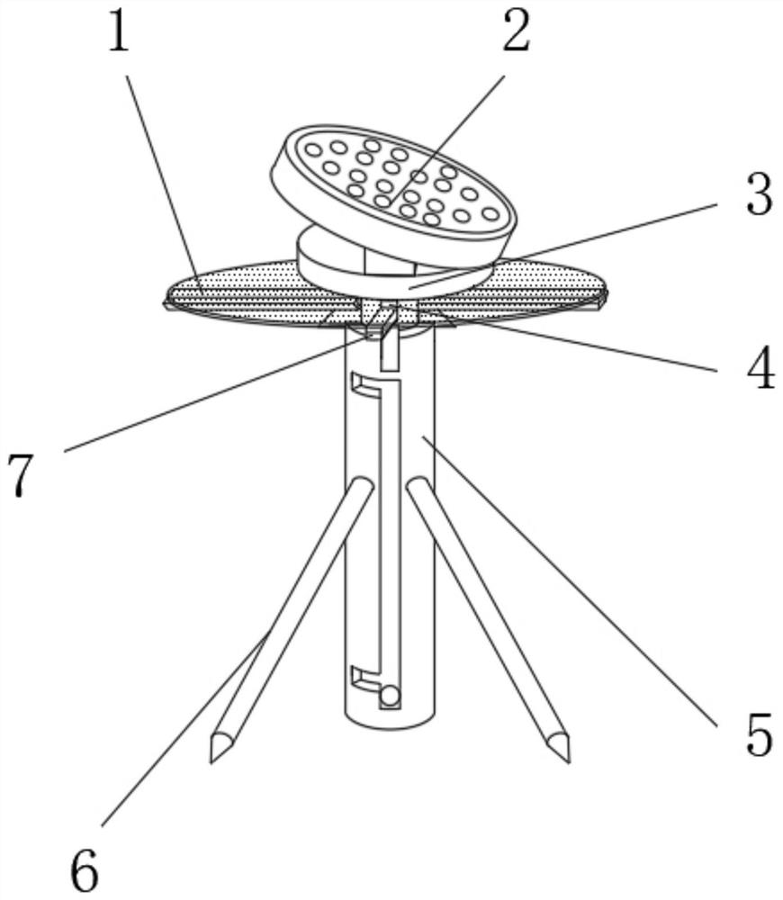
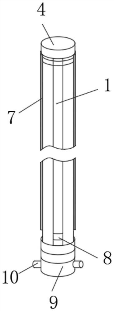
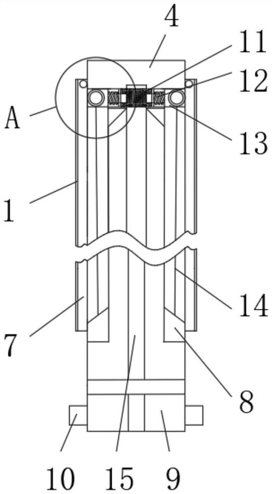
[0047] Such as Figure 1-11 As shown, an LED floodlight includes an LED floodlight 2 and a carrying platform 3, the LED floodlight 2 is fixedly connected to the upper end surface of the carrying platform 3, and the lower end surface of the carrying platform 3 is fixedly connected to an inner sleeve 4, The outer end surface of the inner casing 4 is rotatably connected with a shielding rod 7, the upper end surface of the shielding rod 7 is fixedly connected with a shielding layer 1, the outer end surface of the bearing platform 3 and the shielding rod 7 is sleeved with an outer sleeve 5, and the side end surface of the outer sleeve 5 Fixedly connected with a fixed bracket 6, the lower end surface of the inner casing 4 is rotatably connected with a rotating base 9, the side end surface of the rotating base 9 is fixedly connected with a limit rod 10, and the outer sleeve 5 is equipped with a The fixing groove 27.

[0048] During specific use, the whole device is fixed by the fixi...


PUM


Abstract

The invention discloses an LED projection lamp. The LED projection lamp comprises an LED projection lamp body and a bearing platform, wherein the LED projection lamp body is fixedly connected to the upper end face of the bearing platform, an inner sleeve is fixedly connected to the lower end face of the bearing platform, a shielding rod is rotatably connected to the outer end face of the inner sleeve, a shielding layer is fixedly connected to the upper end face of the shielding rod, the outer end face of the bearing platform and the outer end face of the shielding rod are connected with an outer sleeve in a sleeved mode, the side end face of the outer sleeve is fixedly connected with a fixing support, and the whole LED projection lamp is fixed through the fixing support. According to the invention, the shielding rod is rotated to unfold the shielding layer to cover vegetation around the LED projection lamp so as to prevent the influence of too high vegetation growth on irradiation of the LED projection lamp; and the shielding layer can adopt a black filter screen to maximally inhibit vegetation growth while guaranteeing vegetation survival; and the position of the shielding rod is limited through sleeving of the inner sleeve and the outer sleeve, so the shielding rod is in an unfolded state all the time, and the influence of the periphery of the LED projection lamp on illumination of the lamp is prevented.

Description

technical field [0001] The invention relates to the technical field of lighting equipment, in particular to an LED floodlight. Background technique [0002] LED floodlights are also known as LED spotlights and LED projection lights. LED floodlights are controlled by a built-in microchip. There are currently two types of products, one uses a combination of power chips, and the other uses a single high-power chip. The performance of the former is relatively stable, and the structure of a single high-power product is large, suitable for small Range of light projection, the latter can reach very high power, and can carry out long-distance large-area light projection. LED floodlights make the illuminance on the designated illuminated surface higher than that of the surrounding environment, also known as spotlights. Generally, it is capable of aiming in any direction and has a structure that is not affected by climatic conditions. It is mainly used for large-area operation site...

Claims


Application Information

Patent Timeline
Patent Type & Authority Applications(China)
IPC IPC(8): F21S8/08F21V33/00A01D34/63A01D34/73A01D34/82A01G7/06F21Y115/10
CPCF21S8/08F21V33/00A01D34/63A01D34/73A01D34/82A01G7/06F21Y2115/10
Inventor 沈驹辉丁振桥王裕峰
Why Eureka
Try Eureka