Rubber tire online detection equipment
A technology of rubber tires and testing equipment, which is applied in the direction of automobile tire testing, testing wear resistance, etc., can solve the problem that the wear resistance of rubber tires cannot be simulated, the reliability of the wear resistance test results of rubber tires is low, and the wear resistance test cannot be satisfied and other problems, to achieve the effect of fast response, stable avoidance
- Summary
- Abstract
- Description
- Claims
- Application Information
AI Technical Summary
Problems solved by technology
Method used
Image

Examples
Embodiment 1
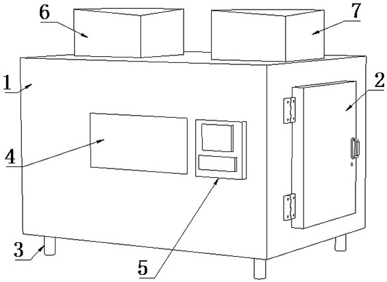
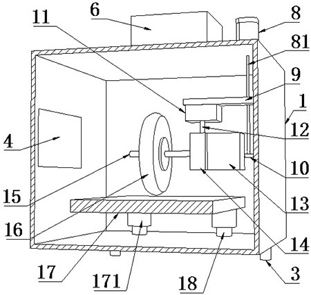
[0063] Such as Figure 1-2 as well as Figure 6 As shown, a kind of rubber tire on-line detection equipment proposed by the present invention includes a housing 1, a sliding plate 9, a rotating shaft 12, a first protection box 13, a driving device A, a mounting plate 14, a mounting shaft 15, a friction plate 17, multiple A support portion 18, a plurality of load cells 31 and an online detection system;
[0064] The bottom surface of the casing 1 is provided with a plurality of support columns and a waste discharge pipe; a control valve is provided on the waste discharge pipe; the bottom surface of the casing 1 is inclined downward toward the central axis of the waste discharge pipe, and then the inside of the casing 1 is cleaned or drained. , so that the impurities in the shell 1 can be quickly discharged from the miscellaneous discharge pipe; the shell 1 is provided with a heating device 6 for heating the inside of the shell 1 and a refrigeration device 7 for cooling the ins...
Embodiment 2
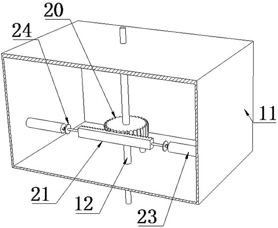
[0100] Such as Figure 3-4 As shown, the present invention proposes a rubber tire on-line detection device. Compared with Embodiment 1, this embodiment also includes the specific structure of the adjustment assembly; the adjustment assembly includes the second protection box 11, the gear 20, the rack 21, the drive Component A and drive component B;
[0101] The rotating shaft 12 is rotatably connected to the second protective box 11 and runs through the second protective box 11; the second protective box 11 is connected to the sliding plate 9; the gear 20 is connected to the rotating shaft 12, and the gear 20 is meshed and connected to the rack 21; the rack 21 is slidably connected to the second The inner wall of the second protection box 11;
[0102]The driving assembly A and the driving assembly B are respectively located on both sides of the rack 21, the driving ends of the driving assembly A and the driving assembly B are connected to both sides of the rack 21, and the fi...
Embodiment 3
[0112] Such as Figure 5 As shown, a kind of rubber tire on-line detection equipment proposed by the present invention, compared with Embodiment 1, this embodiment also includes the specific structure of the jacking assembly; each jacking assembly includes a pressure sensor 19, a telescopic device 29, a moving Part 30, a plurality of sliding parts 32, a plurality of tightening rods 33 and a plurality of springs B34;
[0113] Each support portion 18 is provided with an installation warehouse; each installation warehouse is provided with a plurality of second through holes on each support portion 18; the second through hole is provided with a sealing guide sleeve B; the seal guide sleeve B interferes Sleeved on the outside of the tightening rod 33;
[0114] A plurality of sliding parts 32 are all slidably connected to the inner wall of the installation compartment. The plurality of sliding parts 32 are evenly distributed around the center axis of the support part 18, and each s...
PUM
 Abstract
Description
Claims
Application Information
 - R&D
- Intellectual Property
- Life Sciences
- Materials
- Tech Scout
- Unparalleled Data Quality
- Higher Quality Content
- 60% Fewer Hallucinations
Browse by: Latest US Patents, China's latest patents, Technical Efficacy Thesaurus, Application Domain, Technology Topic, Popular Technical Reports.
© 2025 PatSnap. All rights reserved.Legal|Privacy policy|Modern Slavery Act Transparency Statement|Sitemap|About US| Contact US: help@patsnap.com