Mutual inductor turn number conversion device

A technology of conversion device and transformer, applied in the direction of measuring device, measuring device casing, instrument, etc., can solve the problems of small output current of the tester, the inability to miniaturize the size, and slow down the acceptance time, so as to improve the efficiency and ensure the service life. , easy to use effect

Pending Publication Date: 2021-09-03
STATE GRID ZHEJIANG ELECTRIC POWER CO LTD JINHUA POWER SUPPLY CO
View PDF0 Cites 0 Cited by
  • Summary
  • Abstract
  • Description
  • Claims
  • Application Information

AI Technical Summary

Problems solved by technology

[0002] At present, the acceptance method of high-voltage current transformers on the market is to apply an equivalent current according to the rated primary current of the current transformer, and then judge whether the transformer meets the requirements by detecting the secondary output current value of the transformer. This experiment requires a large Due to power reasons, current generators and large current generators often cannot be miniaturized in size. Excessive volume and weight have brought great changes to field testers. Currently, for the acceptance of feedthrough transformers, field testers The method is to increase the primary winding of the transformer to meet the problem of small output current of the conventional relay tester
However, the one-time winding process of the core-through transformer is cumbersome. When encountering a transformer with a large rated current, it is often necessary to wind dozens of turns of the current wire, which greatly slows down the acceptance time on site.

Method used


Image

  • Mutual inductor turn number conversion device
  • Mutual inductor turn number conversion device
  • Mutual inductor turn number conversion device

Examples


Embodiment Construction

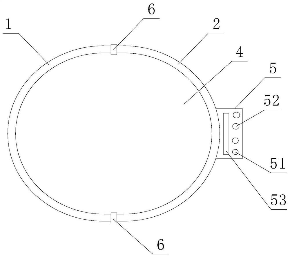
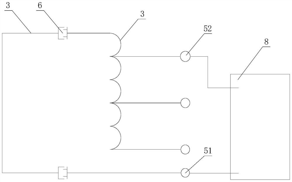
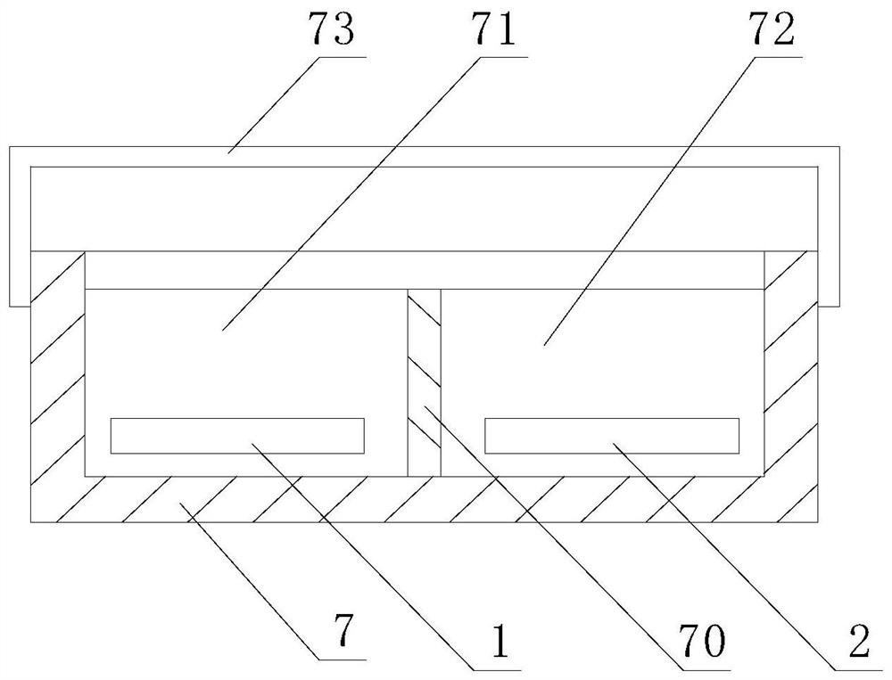
[0020] Such as figure 1 , figure 2 , image 3 As shown, a device for changing the number of turns of a transformer includes a first shell 1 and a second shell 2 connected to each other, and coil windings 3 are arranged in the first shell 1 and the second shell 2, and the first shell 1 and the second shell 2 form a central hole 4 for the transformer to pass through. The first shell 1 or the second shell 2 is provided with a connecting socket 5 connected to a relay 8, and the connecting socket 5 includes A common connection terminal 51, and at least two adjustment terminals 52 showing different turns of the coil winding 3, the adjustment terminals 52 are connected to the coil winding 3, the vertical axes of each adjustment terminal 52 do not coincide, and each adjustment terminal 52 The diameters of the transformers are not equal, and the number of turns of the primary winding of the transformer is changed by connecting the adjustment terminals 52 with different turns.

[00...


PUM


Abstract

The invention relates to a mutual inductor turn number conversion device which comprises a first shell and a second shell, coil windings are arranged in the first shell and the second shell, a center hole is formed between the first shell and the second shell, a connecting socket is arranged on the first shell or the second shell, and the connecting socket comprises a common connecting terminal and an adjusting terminal; the mutual inductor turn number conversion device has the advantages that the mutual inductor needing to be accepted and inspected penetrates through the center hole formed by assembling the first shell and the second shell and is connected with the relay protection instrument through the connecting socket on the first shell or the second shell, and due to the fact that the adjusting terminal on the connecting socket can display coil windings with different numbers of turns, during inspection, the number of turns of the primary winding penetrating through the mutual inductor can be changed only by connecting different adjusting terminals, so that the magnetic coupling of the mutual inductor is changed, tests of current mutual inductors of various specifications are completed under the condition that the actual output primary current value is not changed, and the inspection and acceptance efficiency of the mutual inductor is improved.

Description

technical field [0001] The invention relates to a device for changing the number of turns of a transformer. Background technique [0002] At present, the acceptance method of high-voltage current transformers on the market is to apply an equivalent current according to the rated primary current of the current transformer, and then judge whether the transformer meets the requirements by detecting the secondary output current value of the transformer. This experiment requires a large Due to power reasons, current generators and large current generators often cannot be miniaturized in size. Excessive volume and weight have brought great changes to field testers. Currently, for the acceptance of feedthrough transformers, field testers The method is to increase the primary winding of the transformer to meet the problem of small output current of the conventional relay tester. However, the one-time winding process of the core-through transformer is cumbersome. When encountering a...

Claims


Application Information

Patent Timeline
Patent Type & Authority Applications(China)
IPC IPC(8): G01R35/02G01R1/04
CPCG01R35/02G01R1/04G01R1/0416
Inventor 林恺丰方旭光杨昶宇陈建华朱泽厅卢鸣凯吴昊姚越赵康同周舒婷徐勇俊胡李栋金超郑庆徐良凯徐永昶吴学雷沈然吴慧姜宇航胡有斌
Owner STATE GRID ZHEJIANG ELECTRIC POWER CO LTD JINHUA POWER SUPPLY CO
Why Eureka
Try Eureka