Automatic feeding precision compensation mechanism of numerical control machine tool

A technology of automatic feeding and precision compensation, applied in automatic control devices, metal processing machinery parts, metal processing, etc., can solve problems such as poor response efficiency, affecting product feeding compensation accuracy, and inability to grasp the tool spindle distance, etc., to improve The effect of compensation accuracy, improved automation level, and convenient and flexible observation

Inactive Publication Date: 2021-09-07
江美平
View PDF0 Cites 0 Cited by
  • Summary
  • Abstract
  • Description
  • Claims
  • Application Information

AI Technical Summary

Problems solved by technology

[0003] In order to solve the problems raised in the above-mentioned background technology, the purpose of the present invention is to provide an automatic feeding accuracy compensation mechanism for CNC machine tools, which has the advantage of improving the feeding compensation accuracy, and solves the problem that the existing compensation methods are mostly through adjusting the vertical height of the tool. Adjustment, this method has poor response efficiency, and the operator cannot grasp the distance of the tool extending from the spindle, which affects the accuracy of product feeding compensation

Method used


Image

  • Automatic feeding precision compensation mechanism of numerical control machine tool
  • Automatic feeding precision compensation mechanism of numerical control machine tool
  • Automatic feeding precision compensation mechanism of numerical control machine tool

Examples


Embodiment 1

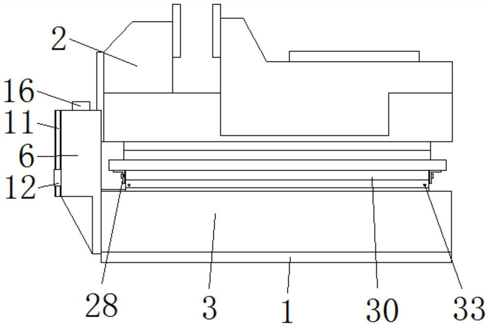
[0029] The present invention provides a CNC machine tool automatic feeding accuracy compensation mechanism, including a connecting plate 1 for installing the structure;

[0030] a fixture 2 arranged on the top of the connecting plate 1 for clamping the workpiece;

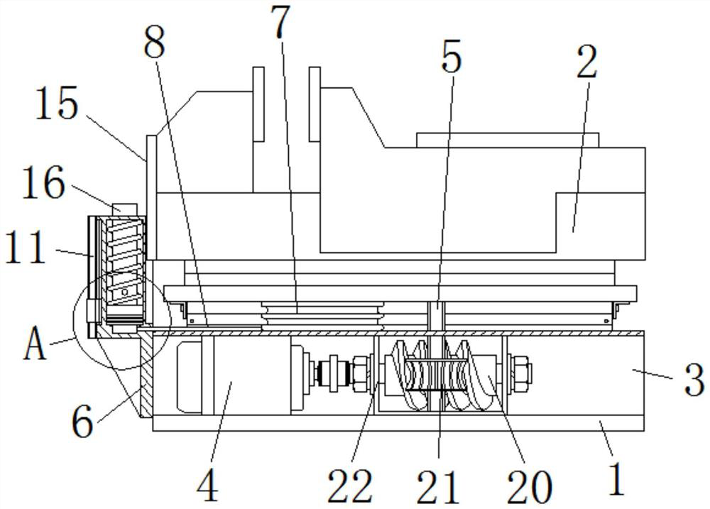
[0031] The top of the connection plate 1 is fixedly connected with the support frame 3, the top of the connection plate 1 is fixedly connected with the transmission motor 4 inside the support frame 3, the output end of the transmission motor 4 is fixedly connected with a structure for driving the screw 5 to rotate, the connection plate 1 The top of the screw rod 5 is movably connected to the screw rod 5 through the bearing, and the top of the screw rod 5 runs through the support frame 3 and the tooling fixture 2 in turn and extends to the inside of the tooling fixture 2. Structure for measuring compensation values.

[0032] refer to Figure 6 , the structure used to measure the compensation value is a measuring bo...

Embodiment 2

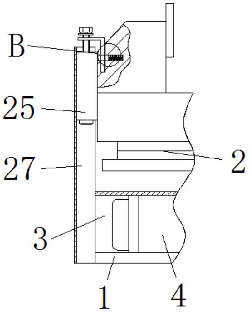
[0047] Such as Figure 7 As shown, in the second embodiment, other structures remain unchanged, and the present invention provides another structure for measuring the compensation value, which includes an opening 23 provided on the top of the fixture 2, and the inside of the opening 23 is slidingly connected with The hook 24, the side of the hook 24 away from the opening 23 runs through the opening 23 and extends to the left side of the fixture 2, the bottom of the hook 24 is provided with an infrared rangefinder 25 located on the left side of the fixture 2, the infrared rangefinder 25 and the tooling The clamps 2 are arranged vertically and parallel to each other, the top of the hook 24 is provided with a bolt 26, and the bottom of the bolt 26 runs through the hook 24 and the infrared range finder 25 in turn and extends to the inside of the infrared range finder 25, the bolt 26 is threaded with the hook 24, The bolt 26 and the infrared range finder 25 are flexibly connected t...

Embodiment 3

[0050] Such as Figure 7 As shown, in the third embodiment, other structures remain unchanged, and the present invention provides another structure for limiting and guiding the fixture 2, including a sleeve 27 fixed on the left side of the support frame 3, the sleeve The top of 27 extends upwards to the left side of the fixture 2. The infrared rangefinder 25 is located inside the sleeve 27 and contacts the inner surface of the sleeve 27. The infrared rangefinder 25 can slide up and down inside the sleeve 27 to connect.

[0051] During use, the transmission motor 4 drives the worm wheel 21 to rotate through the worm 20, and the worm wheel 21 drives the screw 5 to rotate and pushes the fixture 2 to move downward through the threads on the surface of the screw 5, and the fixture 2 drives the infrared rangefinder 25 to move and The distance between it and the working platform is reduced, and the casing 27 can protect the infrared rangefinder 25, reduce the impact of external light...


PUM


Abstract

The invention discloses an automatic feeding precision compensation mechanism of a numerical control machine tool. The automatic feeding precision compensation mechanism comprises a connecting plate used for installing a structure and a tool clamp arranged at the top of the connecting plate and used for clamping a workpiece, a supporting frame is fixedly connected to the top of the connecting plate, and a transmission motor located in the supporting frame is fixedly connected to the top of the connecting plate. The output end of the transmission motor is fixedly connected with a structure used for driving a screw to rotate, the top of the connecting plate is movably connected with the screw through a bearing, the top end of the screw sequentially penetrates through the supporting frame and the tool clamp and extends into the tool clamp, and the tool clamp is in threaded connection with the screw. The left side of the supporting frame is fixedly connected with a structure used for measuring a compensation value. The problems that the vertical height of a cutter is mostly adjusted according to a compensation mode in the prior art, the response efficiency is poor, an operator cannot master the distance of the cutter extending out of a main shaft, and the product feeding compensation precision is affected are solved.

Description

technical field [0001] The invention relates to the technical field of numerical control machine tools, in particular to an automatic feeding accuracy compensation mechanism for numerical control machine tools. Background technique [0002] CNC machine tools need to compensate the machining height according to the installation height of the material after loading. Most of the existing compensation methods are to adjust the vertical height of the tool. This method has poor response efficiency and the operator cannot adjust the tool extension. The distance of the main shaft is mastered, which affects the accuracy of product feeding compensation. Contents of the invention [0003] In order to solve the problems raised in the above-mentioned background technology, the purpose of the present invention is to provide an automatic feeding accuracy compensation mechanism for CNC machine tools, which has the advantage of improving the feeding compensation accuracy, and solves the pr...

Claims


Application Information

Patent Timeline
Patent Type & Authority Applications(China)
IPC IPC(8): B23Q15/24
CPCB23Q15/24
Inventor 江美平
Owner 江美平
Why Eureka
Try Eureka