Mounting structure of parking air conditioner and control method thereof
A technology of installation structure and control method, which is applied to vehicle parts, transportation and packaging, air treatment equipment, etc., and can solve problems such as poor shock absorption performance and unstable installation
- Summary
- Abstract
- Description
- Claims
- Application Information
AI Technical Summary
Problems solved by technology
Method used
Image
Examples
Embodiment 1
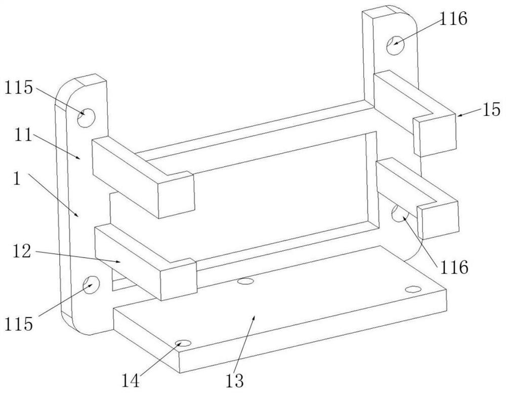
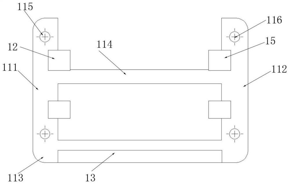
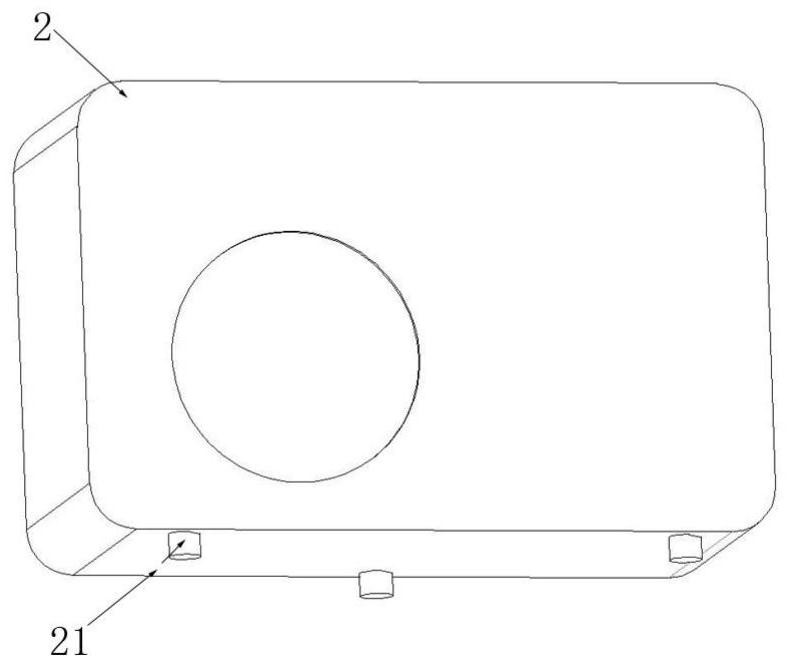
[0051] This embodiment proposes an installation structure for a parking air conditioner, such as Figure 1-6 As shown, the installation structure is used to install the outdoor unit 2 of the parking air conditioner, specifically, as figure 1 and figure 2 As shown, the installation structure includes a mounting frame 1, and the mounting frame 1 includes a mounting plate 11, and the front panel of the mounting plate 11 extends a first fixing portion 12, a second fixing portion 12, and a second fixing portion in a direction away from the cab 9. part 13 and the third fixing part 15; the mounting plate 11, the first fixing part 12, the second fixing part 13, the third fixing part 15 and a housing cavity are formed between them, as Figure 6 As shown, the outdoor unit 2 is installed in the accommodating cavity formed by the mounting frame 1, the first fixing part 12 and the third fixing part 15 fix the outdoor unit 2 in the horizontal direction, and the second fixing part 13 fixes...
Embodiment 2
[0068] On the basis of Embodiment 1, in order to further improve the stability and shock absorption performance of the outdoor unit 2 installation, as Figure 7 As shown, a shock-absorbing clamping device 6 is provided on the mounting frame 1 . The setting of the shock-absorbing clamping device 6 effectively buffers the vibration effect that the shaking of the car brings to the outdoor unit 2, so that the connection between the mounting frame 1 and the outdoor unit 2 is not easy to loosen.
[0069] More specifically, such as Figure 8As shown, the shock absorbing clamping device 6 includes an elastic member 61, a clamping block 62 and a shock absorbing block 63, the elastic member 61 is connected to the mounting frame 1, and one end of the clamping block 62 is connected to the elastic member 61 , the other end of the clamping block 62 is connected to the shock absorbing block 63 , and the shock absorbing block 63 is in contact with the outdoor unit 2 . The arrangement of the...
Embodiment 3
[0072] On the basis of Embodiment 2, in order to further improve the stability and shock absorption performance of the outdoor unit 2 installation, as Figure 9 , 10 As shown in and 11 , an installation cover 4 is arranged on the outside of the installation frame 1 , and the installation cover 4 is connected with the cab 9 . The setting of the installation cover 4 can fully cover the installation frame 1 and the outdoor unit 2, which increases the protection effect of the installation frame 1 and the outdoor unit 2, and prevents hard objects such as external stones from directly hitting the installation frame 1 and the outdoor The main body of the machine 2 increases safety, and can prevent the mounting frame 1 and the outdoor machine 2 from falling from the car by covering it comprehensively.
[0073] The inside of the cover body 40 of the installation cover 4 forms an installation cavity for installing the installation frame 1 and the outdoor unit 2 . The inner wall surfac...
PUM
 Abstract
Description
Claims
Application Information
 - R&D
- Intellectual Property
- Life Sciences
- Materials
- Tech Scout
- Unparalleled Data Quality
- Higher Quality Content
- 60% Fewer Hallucinations
Browse by: Latest US Patents, China's latest patents, Technical Efficacy Thesaurus, Application Domain, Technology Topic, Popular Technical Reports.
© 2025 PatSnap. All rights reserved.Legal|Privacy policy|Modern Slavery Act Transparency Statement|Sitemap|About US| Contact US: help@patsnap.com


