A condiment packaging bag packaging coding integrated automation equipment
A technology of automatic equipment and packaging bags, which is applied in the directions of packaging, transportation packaging, transportation and packaging, can solve the problems of opening the packaging bags of seasoning packets, increasing the production cost of seasonings, affecting the sealing quality of packaging bags of seasoning packets, etc. It is easy to apply glue and encapsulate and ensure the effect of sealing quality.
- Summary
- Abstract
- Description
- Claims
- Application Information
AI Technical Summary
Problems solved by technology
Method used
Image
Examples
Embodiment 1
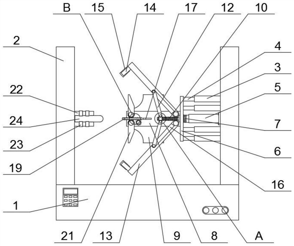
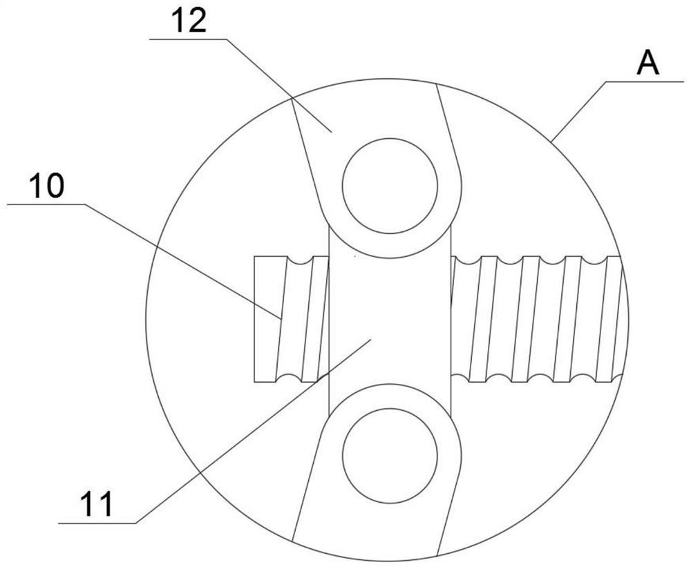
[0024] Example 1, refer to Figure 1-5, an integrated automatic equipment for packaging and coding of condiment packaging bags, comprising a machine base 1, two sets of racks 2 installed on the upper end of the machine base 1 and distributed symmetrically, and two sets of frame plates 22 installed on one of the sets of racks 2 , The transmission roller 23 connected to the frame plate 22 in rotation and the clamping mechanism 24 slidably connected between the two sets of frame plates 22, the inner end of the other group of frame 2 is installed with a hydraulic rod 5, and the free end of the hydraulic rod 5 A hanging plate 6 is fixedly connected, and a mounting seat 8 is fixedly connected to the side of the hanging plate 6 away from the hydraulic rod 5. The outer end of the mounting seat 8 is installed with two sets of glue nozzles 9 that are symmetrically distributed, and the outer end of the mounting seat 8 is far away from the hydraulic rod 5. One side of the hanging plate 6 ...
Embodiment 2
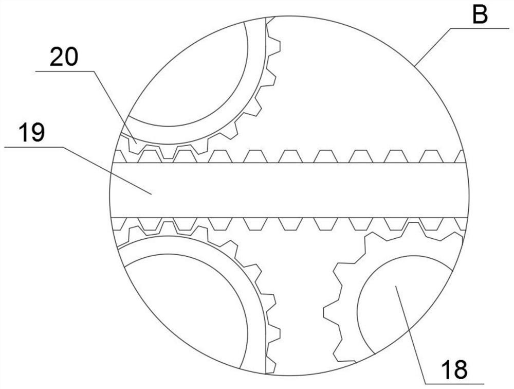
[0025] Embodiment 2, refer to figure 1 , image 3 , Figure 4 and Figure 5 , the outer end of the mounting seat 8 is rotatably connected with the drive gear 18, the interior of the mounting seat 1 is mounted with a motor that cooperates with the drive gear 18, the outer end of the mounting seat 1 is slidably connected with a rack 19, and the rack 19 and the drive gear 18 The inner ends of the two sets of support arms 21 are fixedly connected with the driven gear 20 on the outside of the rotating shaft, and the driven gear 20 is meshed with the rack 19. The motor located inside the mounting seat 8 drives the driving gear 18 to rotate, which in turn drives the driving gear 18 to rotate. The rack 19 meshed with the drive gear 18 slides in reverse to the outside of the base 1 along the slide rail 17. When the rack 19 slides in the horizontal direction, it drives the two sets of driven gears 20 meshed with it to perform a synchronous reversal. When rotating, the driven gear 20 ...
Embodiment 3
[0026] Embodiment 3, refer to figure 1 , the outer end of the mounting seat 8 is fixedly connected with a slide rail 17 that cooperates with the rack 19 to slide, and the inside of the clamp arm 13 has a turning groove 16 that cooperates with the clamp arm 13 to rotate. The setting of the slide rail 17 makes the sliding of the rack 19 more stable , to prevent the rack 19 from falling off the mounting seat 8 during the transmission process, and the setting of the turning slot 16 is located on the support rod 12 to provide a rotation space, so that the device runs smoothly.
PUM
 Abstract
Description
Claims
Application Information
 - R&D
- Intellectual Property
- Life Sciences
- Materials
- Tech Scout
- Unparalleled Data Quality
- Higher Quality Content
- 60% Fewer Hallucinations
Browse by: Latest US Patents, China's latest patents, Technical Efficacy Thesaurus, Application Domain, Technology Topic, Popular Technical Reports.
© 2025 PatSnap. All rights reserved.Legal|Privacy policy|Modern Slavery Act Transparency Statement|Sitemap|About US| Contact US: help@patsnap.com


