
Wire cutting device for electronic circuit board welding

An electronic circuit board and cutting device technology, applied in the directions of printed circuits, printed circuit manufacturing, and assembling printed circuits with electrical components, can solve the problems of spending a lot of time, manpower and material resources, failing to improve work efficiency, and increasing working time.

Active Publication Date: 2019-06-07
山东省阳信铭泰电气有限公司
View PDF8 Cites 0 Cited by
  • Summary
  • Abstract
  • Description
  • Claims
  • Application Information

AI Technical Summary

Problems solved by technology

[0002] With the development of our country's economy, our country has put forward the policy of manufacturing 2025. The country pays more and more attention to the automation industry and strongly supports the automation process of the industry. In this process, the hardware industry will develop vigorously, and the electronic circuit board is the basis of hardware. , the demand has increased in a blowout manner. The entire hardware industry needs to manufacture a large number of electronic circuit boards. When producing electronic circuit boards in batches, it is necessary to cut off the device pins soldered on the circuit board. This operation process is very complicated and cumbersome. Due to the need to deal with The number of electronic circuit boards is huge, it takes a lot of time and manpower and material resources, increases the cost of hardware manufacturing, and cannot improve work efficiency
[0003] However, at present, in the manufacturing process of electronic circuit boards, the work of cutting the wires of the device pins after welding is manually completed by workers. The protruding extra pins are cut off, the whole process is very complicated and cumbersome, and the part of the trimmed line cannot be guaranteed to be flat, which greatly increases the pressure on the staff, wastes a lot of manpower and material resources, is inefficient, and increases the workload. Time is not conducive to the development of the automation industry

Method used


Image

  • Wire cutting device for electronic circuit board welding
  • Wire cutting device for electronic circuit board welding
  • Wire cutting device for electronic circuit board welding

Examples


Embodiment Construction

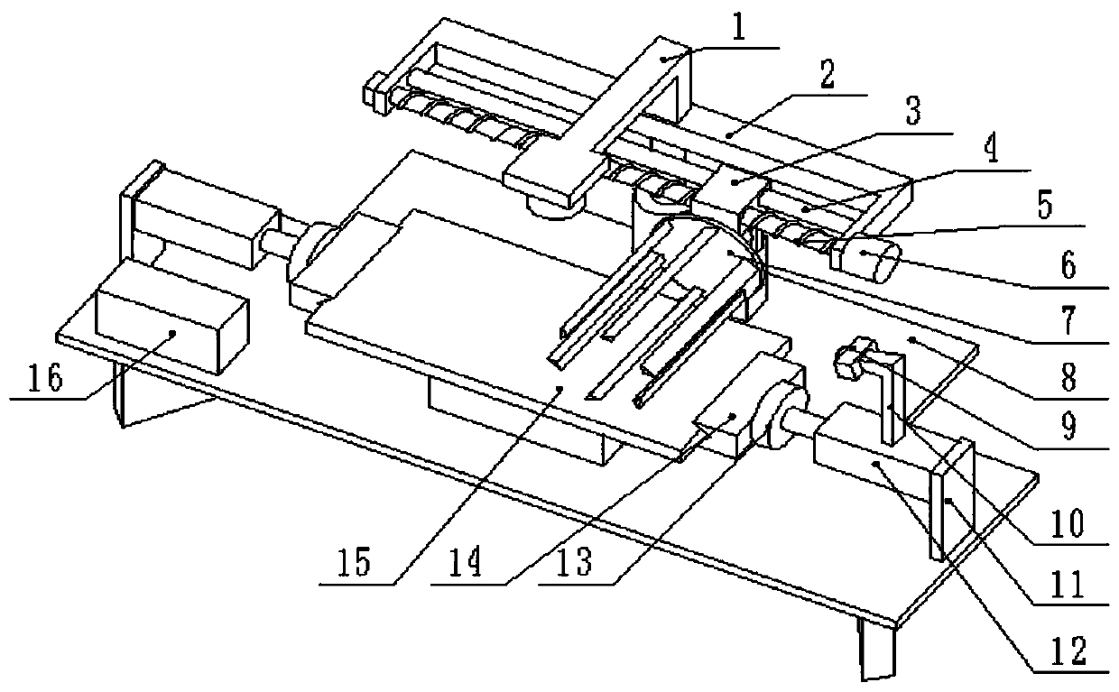
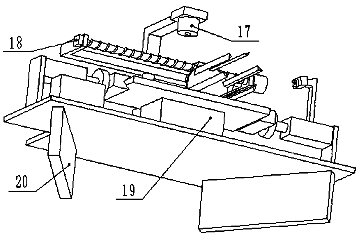
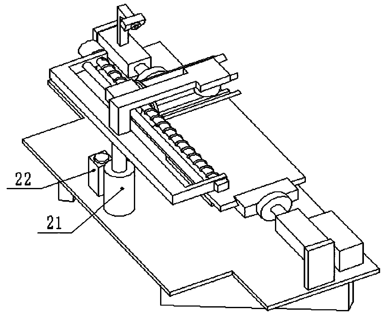
[0017] The present invention is achieved through the following technical solutions: a wire cutting device for electronic circuit board welding, comprising a first bracket 1, a second bracket 2, a slider 3, a slide rail 4, a lead screw 5, a first motor 6, a cutting Device 7, workbench 8, camera 9, camera base 10, hydraulic cylinder base 11, first hydraulic cylinder 12, pressure sensor 13, push block 14, processing plate 15, controller 16, first ultrasonic sensor 17, code device 18, support table 19, legs 20, second hydraulic cylinder 21, second ultrasonic sensor 22 and second motor 23, the lower part of the workbench 8 is fixedly connected with the legs 20, and the upper side of the workbench 8 is fixed There are hydraulic cylinder bases 11, the number of which is 2, the front left side of the workbench 8 is fixedly connected to the controller 16, the upper middle of the workbench 8 is fixedly connected to the support platform 19, and the inner side of the hydraulic cylinder bas...


PUM


Abstract

The invention discloses a wire shearing device for welding of electronic circuit boards, and belongs to the field of electronic hardware equipment. The device is characterized in that the upper portion of a first hydraulic cylinder on the right side is fixedly connected with a camera base, and the left side of the top end of the camera base is fixedly connected with a camera; and the middle position of the rear side of the upper portion of a workbench is fixedly connected with a second hydraulic cylinder, a lead screw and a sliding rail penetrate through a sliding block, the front side of thelower portion of the sliding block is fixedly connected with a second motor, and the front end of the second motor is fixedly connected with a cutting device. According to the device, through drivingof the hydraulic cylinders and through the cutting device, the wire shearing work of the electronic circuit boards during welding is completed, so that the back surfaces of the electronic circuit boards are flat, and the later operation such as the gluing operation and the packaging operation are facilitated; and the whole process is very simple and convenient in operation, manual operation of workers is not needed, so that the pressure of the workers is reduced, the manufacturing efficiency of the electronic circuit boards is greatly improved, manpower and material resources are saved, the electronic circuit boards can be conveniently manufactured in batches, and the development of industrial automation is promoted.

Description

technical field [0001] The invention relates to a wire-cutting device for electronic circuit board welding, in particular to a device driven by a hydraulic cylinder and used to complete the wire-cutting work of electronic circuit boards during welding through a cutting device, belonging to the field of electronic hardware equipment . Background technique [0002] With the development of our country's economy, our country has put forward the policy of manufacturing 2025. The country pays more and more attention to the automation industry and vigorously supports the automation process of the industry. In this process, the hardware industry will develop vigorously, and the electronic circuit board is the basis of hardware. , the demand has increased in a blowout manner. The entire hardware industry needs to manufacture a large number of electronic circuit boards. When producing electronic circuit boards in batches, it is necessary to cut off the device pins soldered on the circ...

Claims


Application Information

Patent Timeline
Patent Type & Authority Patents(China)
IPC IPC(8): B21F11/00H05K3/34
CPCB21F11/00H05K3/341H05K2203/0228
Inventor 刘畅
Owner 山东省阳信铭泰电气有限公司
Learn More