Eureka AIR delivers breakthrough ideas for toughest innovation challenges, trusted by R&D personnel around the world.

Gas-assisted forming method for producing ultra-oleophobic surface

A gas-assisted, super-oleophobic technology, which is used in the preparation of super-oleophobic surfaces, gas-assisted forming methods, and the preparation of polymer super-oleophobic surfaces, can solve complex preparation processes, unstable super-oleophobic states, and high prices. and other problems, to achieve the effects of low preparation cost, easy batch preparation, and simple equipment

Inactive Publication Date: 2013-04-10
JIANGSU UNIV
View PDF6 Cites 15 Cited by
  • Summary
  • Abstract
  • Description
  • Claims
  • Application Information

AI Technical Summary

Problems solved by technology

Although the Bosch process can control the shape of micro-nano structures well, it has not been widely used in the preparation of super-oleophobic surfaces because it requires more expensive equipment and stricter vacuum conditions.
The cost of the electrospinning method has advantages, but the secondary groove structure it produces is formed by randomly deposited nanoscale filaments, so this method has two limitations: one is the controllability and reproducibility of the secondary groove structure The second is that the secondary groove structure formed by nanoscale filaments is not obvious enough, so when the free energy of the droplet fluctuates, it is easy to damage the Cassie contact interface between the droplet and the surface. (that is, the super-oleophobic state transition phenomenon), making the super-oleophobic state unstable
[0004] In short, the difficulty in preparing superoleophobic surfaces lies in the structure of the secondary groove structure, while the current Bosch process for preparing superoleophobic surfaces requires expensive equipment and the preparation process is complicated. Electrospinning method to prepare secondary groove structures poor controllability

Method used


Image

  • Gas-assisted forming method for producing ultra-oleophobic surface
  • Gas-assisted forming method for producing ultra-oleophobic surface
  • Gas-assisted forming method for producing ultra-oleophobic surface

Examples


Embodiment

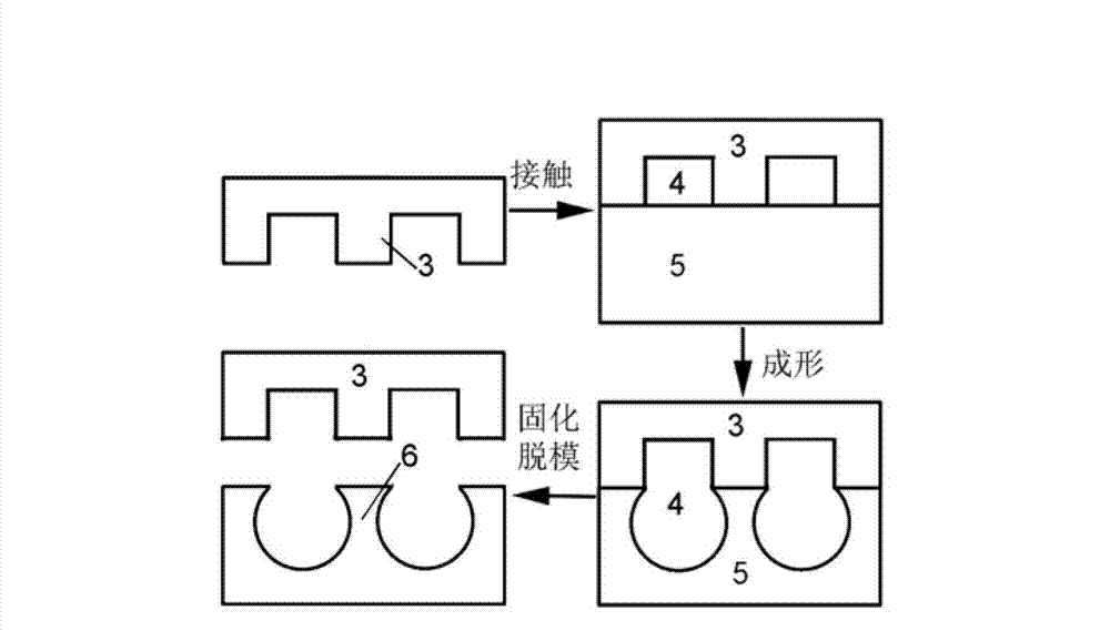
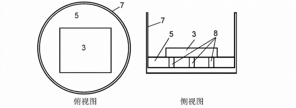
[0032] The hole array template is selected, the hole diameter is 50 μm, the hole spacing is 70 μm, the hole depth is 50 μm, and silicon material is prepared by photolithography. The container is made of glass. The liquid polymer is PDMS. Positioning block 8 selects the positioning block that thickness is 2mm for use.

[0033] The preparation process of PDMS is as follows: firstly weigh the two formulations of PDMS according to the ratio of 10:1, mix the two formulations thoroughly and pour a small amount into a glass dish. Before pouring, the glass dish needs to be placed horizontally, put the three positioning blocks into the glass dish, pay attention when pouring, and stop pouring when the PDMS just submerges the positioning block. Then place the prepared template horizontally on the three positioning blocks. Transfer the container to a vacuum drying oven, taking care to ensure that the bottom of the glass dish is level. according to Calculate the vacuum pressure, subs...


PUM

PropertyMeasurementUnit
thicknessaaaaaaaaaa
thicknessaaaaaaaaaa

Abstract

The invention relates to the technical field of production of functional surfaces, in particular to a gas-assisted forming method for producing an ultra-oleophobic surface, which is applicable to production of the ultra-oleophobic surface of a polymer, in particular to production of the ultra-oleophobic surface under a simple condition. The gas-assisted forming method for producing the ultra-oleophobic surface comprises the following steps: putting a liquid polymer into a container; covering a porous template on the surface of the liquid polymer, and fixing the position of the porous template so as to expose a part of the surface of the liquid polymer; sending the container into a vacuum drying box, vacuumizing, and expanding air confined between the liquid polymer and template pores under the action of pressure difference to form a spherical crown-shaped pore array; and curing the polymer so as to produce a secondary groove structure. Less equipment is required in the two-step forming method; by the two-step forming method, the ultra-oleophobic surface can be produced under the simple condition; the production cost is low; and batch production is easy.

Description

technical field [0001] The invention relates to the technical field of preparation of functional surfaces, in particular to a gas-assisted forming method for preparing super-oleophobic surfaces, which is suitable for the preparation of polymer super-oleophobic surfaces, especially for the preparation of super-oleophobic surfaces under simple conditions. Background technique [0002] A superoleophobic surface refers to a surface that enables droplets with low surface tension (such as oil droplets) to present a large contact angle (>130°) on its surface. Similar to superhydrophobic surfaces, this surface has excellent self-cleaning and drag reduction properties, especially suitable for oily environments. Therefore, superoleophobic surfaces have received extensive attention in recent years. [0003] Existing literature (a new type of super-oleophobic surface structure design method, national invention patent, application number CN201010132465.4; AhujaA, Taylor J A, Lifton V...

Claims


Application Information

Patent Timeline
Patent Type & Authority Applications(China)
IPC IPC(8): B81C1/00
Inventor 李健
Owner JIANGSU UNIV
Why Eureka
Eureka Blog
Learn More