Blockage clearing device for screw conveyor

A screw conveyor and blockage removal technology, which is applied to cleaning devices, conveyor objects, transportation and packaging, etc., can solve the problems of high labor intensity and long time for blockage removal, and achieve power saving, simple structure, and convenient connection.

Active Publication Date: 2021-09-07
章丘华明水泥新型建材有限公司
View PDF10 Cites 1 Cited by
  • Summary
  • Abstract
  • Description
  • Claims
  • Application Information

AI Technical Summary

Problems solved by technology

The existing blockage removal method is to stop the equipment first, then disassemble the casing of the screw conveyor for blockage removal, which has the problems of long time-consuming and labor-intensive cleaning.

Method used


Image

  • Blockage clearing device for screw conveyor
  • Blockage clearing device for screw conveyor
  • Blockage clearing device for screw conveyor

Examples


Embodiment 1

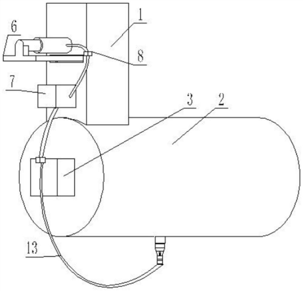
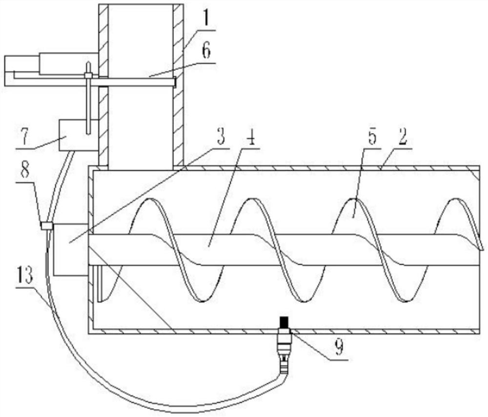
[0034] A screw conveyor clearing device, such as Figure 1-2 As shown, it includes a feeding pipe 1 and a conveying assembly. The feeding pipe 1 is provided with a pneumatic slide valve 6 and an external air source 7. The air source 7 provides power to the pneumatic slide valve 6, and the pneumatic slide valve The valve 6 is used to close the feeding pipe 1 .

[0035] The conveying assembly includes a housing 2, a motor 3, a rotating shaft 4 and a feeding blade 5, the rotating shaft 4 is installed in the housing 2, the rotating shaft 4 is provided with a feeding blade 5, and one side of the housing 2 is provided for driving rotation. The shaft 4 rotates the motor 3, and the side of the housing 2 away from the motor 3 is provided with a discharge port. The motor 3 drives the rotating shaft 4 and the feeding blade 5 to rotate, so as to move the material toward the discharge port.

[0036] The motor 3 is connected to the peripheral controller, and the controller judges the oper...

Embodiment 2

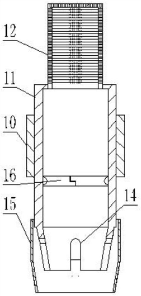
[0050] On the basis of Embodiment 1, two mutually matching sealing plates 16 are movably installed on one end of the installation head 11 close to the filter screen 12, the inner end of the sealing plate 16 is provided with a groove, and the inner end of the other sealing plate 16 is There are convex parts matched with it. The sealing plate 16 maintains a closed state under its own weight, and seals and isolates the interior of the installation head 11, so that the sealing performance of the device can be ensured and material leakage can be prevented when no blockage removal operation is performed.

[0051] An annular support rod 17 is provided at one end of the connecting pipe, and a push rod 18 for lifting the sealing plate 16 is provided on the support rod 17 . Intake pipe 13 inside is provided with support rod 17 and ejector rod 18, and support rod 17 can increase the support strength of connecting pipe, facilitates intake pipe 13 to be inserted on the mounting head 11, av...

Embodiment 3

[0055] On the basis of Embodiment 1 and Embodiment 2, the air intake pipe 13 is provided with a first mark 19 and a second mark 20 . When the user can see that the first mark 19 is located on the lower side of the installation head 11, it means that the air intake pipe 13 is only connected to the installation head 11, but it is not in an effective connection state for the cleaning operation. It has a storage function but does not perform blockage removal operations.

[0056] When the user sees that the second mark 20 is located on the lower side of the installation head 11, it means that the air intake pipe 13 and the installation head 11 are in an effective connection state, and the blockage removal operation can be performed at this time. The mark can serve as a reminder, which is convenient for the staff to confirm the connection status between the intake pipe 13 and the installation head 11, and facilitates work.


PUM


Abstract

The invention discloses a blockage clearing device for a screw conveyor. The blockage clearing device comprises a discharging pipe and a conveying assembly. The discharging pipe is provided with a pneumatic gate valve and an external air source. The conveying assembly is provided with a blockage clearing assembly. An air inlet pipe is installed on one side of the blockage clearing assembly and connected with the air source. Valves are arranged between the air source and the pneumatic gate valve and between the air source and the air inlet pipe correspondingly. The blockage clearing assembly comprises an installation pipe connected with the conveying assembly and an installation head with a filter screen. The installation head is connected with the installation pipe. The filter screen is located in the conveying assembly. The blockage clearing device is simple in structure; when the screw conveyor is blocked, materials at a through hole are cleared away rapidly in time through cooperative use of the pneumatic gate valve and the conveying assembly, the materials are suspended in a shell after blockage clearing, the material conveying safety and conveying efficiency are improved, and the probability that the screw conveyor breaks down or is damaged due to blockage is reduced.

Description

technical field [0001] The invention relates to the technical field of conveyor structures, in particular to a plug-clearing device for a screw conveyor. Background technique [0002] Screw conveyor is a common material conveying device, which uses rotating continuous helical blades to push materials, and is mainly used for conveying cement, fly ash, mineral powder and other powdery, granular and other bulk materials. There is a feeding hopper on one side of the feeding pipe and a discharge port on the other side. After the material enters the conveying pipe, it will gradually move under the push of the screw shaft until it is discharged from the discharge port. [0003] In the conveying system of the horizontal screw conveyor, the material will often be blocked during the conveying process of the screw conveyor, and there will be little or no material output, which will cause the inside of the screw conveyor to be crowded with materials and the screw blades will be overload...

Claims


Application Information

Patent Timeline
Patent Type & Authority Applications(China)
IPC IPC(8): B65G33/26B65G33/24B65G45/10
CPCB65G33/265B65G33/24B65G45/10Y02P70/10
Inventor 部振华韩锋
Owner 章丘华明水泥新型建材有限公司
Why Eureka
Try Eureka