Bridge thin-wall anti-floating design waterproof wall
A waterproof wall and bridge book technology, applied in bridge construction, bridges, bridge parts, etc., can solve the problems of poor impact resistance, damage, and high maintenance difficulty
- Summary
- Abstract
- Description
- Claims
- Application Information
AI Technical Summary
Problems solved by technology
Method used
Image

Examples
Embodiment 1
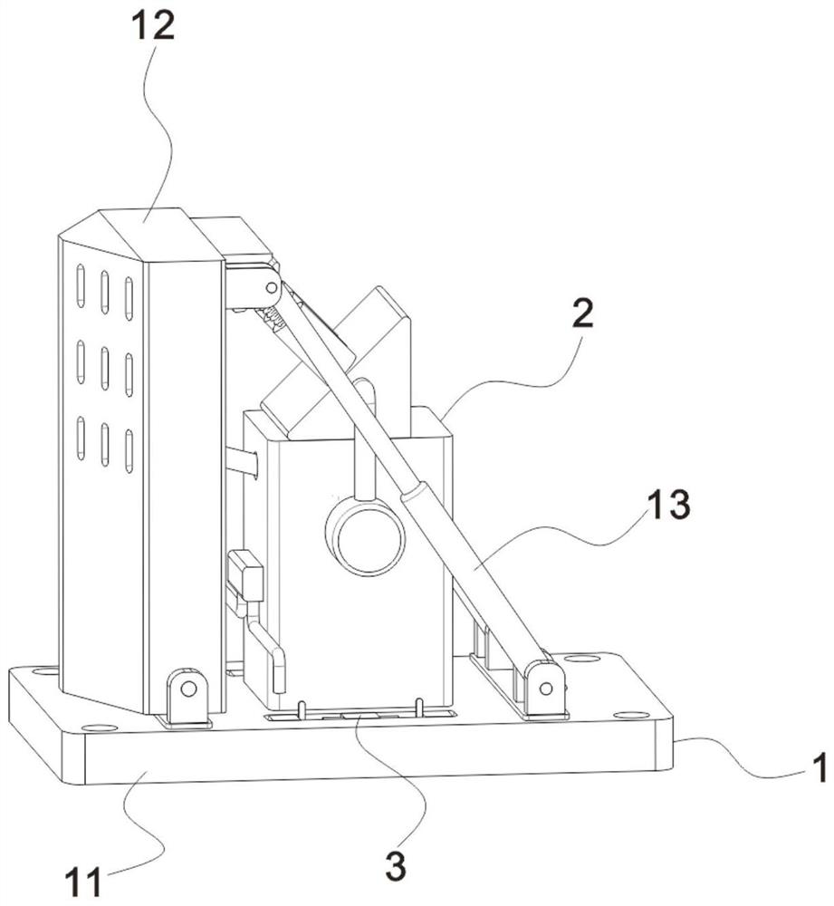
[0024] see Figure 1-4 , the present invention provides bridge thin wall anti-floating design waterproof wall, including,
[0025] The receiving component 1 includes the counterweight base 11, and there are installation holes around the counterweight base 11, which is convenient to fix at the designated position with external fixing parts. The front and rear ends of the right side of the wall panel 12 are hinged to one end of the adjustable support rod 13. The adjustable support rod 13 is widely used in this field and will not be described in detail here. The other end of the adjustable support rod 13 is flexibly connected to the top of the counterweight base 11. ;
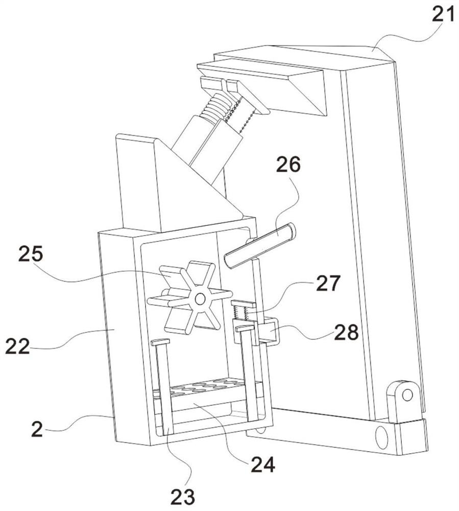
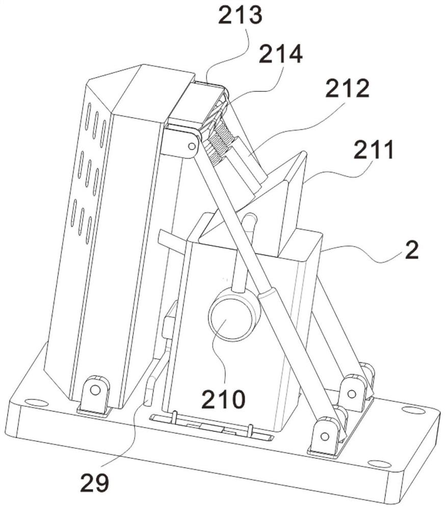
[0026] The slow pressure reinforcement 2, the slow pressure reinforcement 2 includes a triangular guide seat 21 fixed on one side of the waterproof wall panel 12, which guides the impact on the water flow, and a cavity is provided in the guide seat 21 (not shown in the figure). shown), the top of the outer wall ...
Embodiment 2
[0033] see figure 1 with Figure 4 , the maintenance part 3 includes two sets of positioning blocks 31, the left and right sides of the top of the counterweight base 11 are provided with positioning grooves matching the positioning blocks 31, the bottom of the waterproof wall panel 12 is hinged on the top of the left positioning block 31, and the two sets of adjustment support rods 13 The other end is respectively hinged with the front and rear sides of the top of the right positioning block 31, and the front and rear sides of the top of the counterweight base 11 are provided with transverse limiting chute 32, and the limiting chute 32 is located between two sets of positioning blocks 31. 31 and the positioning groove are convenient to play the role of preliminary positioning during installation, and the limiting chute 32 is a T-shaped limiting chute 32;
[0034] see figure 1 with Figure 4 , the middle parts of the two sets of limiting chute 32 are fixed with support block...
PUM
 Abstract
Description
Claims
Application Information
PatSnap Eureka turns technology decisions into work you can execute. Powered by our Innovation Knowledge Graph, it runs expert workflows across engineering, life sciences, materials and intellectual property. Get your review-ready output in minutes.


