Supercharge Your Innovation With Domain-Expert AI Agents!

Hydraulic deep-well pump impeller locking device and mounting method thereof

A technology for locking devices and deep well pumps, which is applied to pump devices, parts of pumping devices for elastic fluids, pumps, etc., and can solve the problem of internal tooth damage of stop washers, loose lock nuts, and affecting normal operation of equipment Operation and other problems, to achieve high reliability and avoid damage

Active Publication Date: 2021-09-07
WUHAN MARINE MACHINERY PLANT
View PDF7 Cites 0 Cited by
  • Summary
  • Abstract
  • Description
  • Claims
  • Application Information

AI Technical Summary

Problems solved by technology

At present, the locking of the impeller and the hub mainly adopts the combined locking of the lock nut and the stop washer, but because there is a certain impact force between the impeller and the hub when the submersible pump is started and stopped in an emergency, if the locking torque of the lock nut Smaller, so that there is a gap between the stop washer and the hub, the lock nut is easy to loose due to long-term vibration, if the lock nut locking torque is large, not only the installation of the stop washer is difficult, but also the stop washer The internal teeth are easily damaged by impact loads, affecting the normal operation of the equipment

Method used


Image

  • Hydraulic deep-well pump impeller locking device and mounting method thereof
  • Hydraulic deep-well pump impeller locking device and mounting method thereof
  • Hydraulic deep-well pump impeller locking device and mounting method thereof

Examples


Embodiment 1

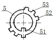
[0041] see Figure 1 to Figure 3, a hydraulic deep well pump impeller locking device, including a pump shaft 1, a hub 2, and an impeller 3 coaxially fixed on the hub 2, the A end 11 of the pump shaft 1 passes through the hub 2 and locks with the inside of the impeller 3 The lock nut 4 is fixedly connected, and the lock nut 4 is an M30*1.5 round nut, and four stop grooves 41 are evenly opened on its outer circumference, and a stop washer is arranged between the upper end surface of the lock nut 4 and the hub 2 5. The inner wall of the stop washer 5 is fixed with an inner tooth 51 matching the keyway 12 on the A end 11, and two outer tooth groups 53 are fixed on the outer circumference, and the outer tooth group 53 includes three and The outer teeth 52 matched with the stop groove 41, the end surface of the A end 11 is provided with a shaft end pressure plate 6 and a fastening assembly 7, and the fastening assembly 7 includes a locking bolt 71 and a self-locking washer 72. The ...

Embodiment 2

[0048] In step 2, the tightening torque is 8Nm, and the width of the gap is 0.02mm;

[0049] In Step 3, the ratio of the loosening torque to the standard tightening torque of the fastening component 7 is 5:10.

Embodiment 3

[0051] In step 2, the tightening torque is 6Nm, and the width of the gap is 0.03mm;

[0052] In Step 3, the ratio of the loosening torque to the standard tightening torque of the fastening component 7 is 4:10.


PUM

PropertyMeasurementUnit
Widthaaaaaaaaaa

Abstract

The invention relates to a hydraulic deep-well pump impeller locking device. A lock washer is arranged between a locking nut and a hub, inner teeth matched with key grooves in an end A are fixed to the inner wall of the lock washer, a plurality of outer teeth matched with locking grooves in the locking nut are fixed to the outer circumference of the lock washer, a shaft end pressing plate is arranged on the end face of the end A, the middle of the shaft end pressing plate is fixedly connected with the end of the A end through a fastening assembly, and the upper end face of the shaft end pressing plate is attached to the lower end face of the locking nut. During installation, the inner teeth are matched with the key grooves firstly, then the locking nut is tightened while it is guaranteed that a gap exists between the lock washer and the hub, then the shaft end pressing plate and the end of the A end are fixed through the fastening assembly, finally, after it is verified that the fastening assembly is tightened to be qualified, the outer teeth are bent downwards and then matched with the locking grooves, and installation is completed. By means of the design, the inner teeth of the lock washer can be prevented from being damaged, it can be guaranteed that the locking nut cannot loosen, and reliability is high.

Description

technical field [0001] The invention belongs to the technical field of impeller locking, and in particular relates to a hydraulic deep well pump impeller locking device and an installation method thereof, which are suitable for preventing lock nuts from being loose while avoiding damage to stop washers. Background technique [0002] As the key equipment in loading and unloading equipment, submersible pumps are widely used on tankers. As the main working components of the submersible pump, the impeller and hub require a stable working environment and a high service life. At present, the locking of the impeller and the hub mainly adopts the combined locking of the lock nut and the stop washer, but because there is a certain impact force between the impeller and the hub when the submersible pump is started and stopped in an emergency, if the locking torque of the lock nut Smaller, so that there is a gap between the stop washer and the hub, the lock nut is easy to loose due to ...

Claims


Application Information

Patent Timeline
IPC IPC(8): F04D13/10F04D29/20F04D29/60B63B27/00
CPCF04D13/10F04D29/20F04D29/605B63B27/00Y02E10/20
Inventor 李战赵雷刚张聪
Owner WUHAN MARINE MACHINERY PLANT
Features
  • R&D
  • Intellectual Property
  • Life Sciences
  • Materials
  • Tech Scout
  • Unparalleled Data Quality
  • Higher Quality Content
  • 60% Fewer Hallucinations
Learn More