Laser radar and ranging method thereof

A technology of laser radar and laser, which is applied in the direction of measuring device, radio wave measurement system, electromagnetic wave re-radiation, etc., can solve the problems of laser beam density, redundancy, overlapping laser spots, etc.

Pending Publication Date: 2021-09-07
HESAI TECH CO LTD
View PDF0 Cites 2 Cited by
  • Summary
  • Abstract
  • Description
  • Claims
  • Application Information

AI Technical Summary

Problems solved by technology

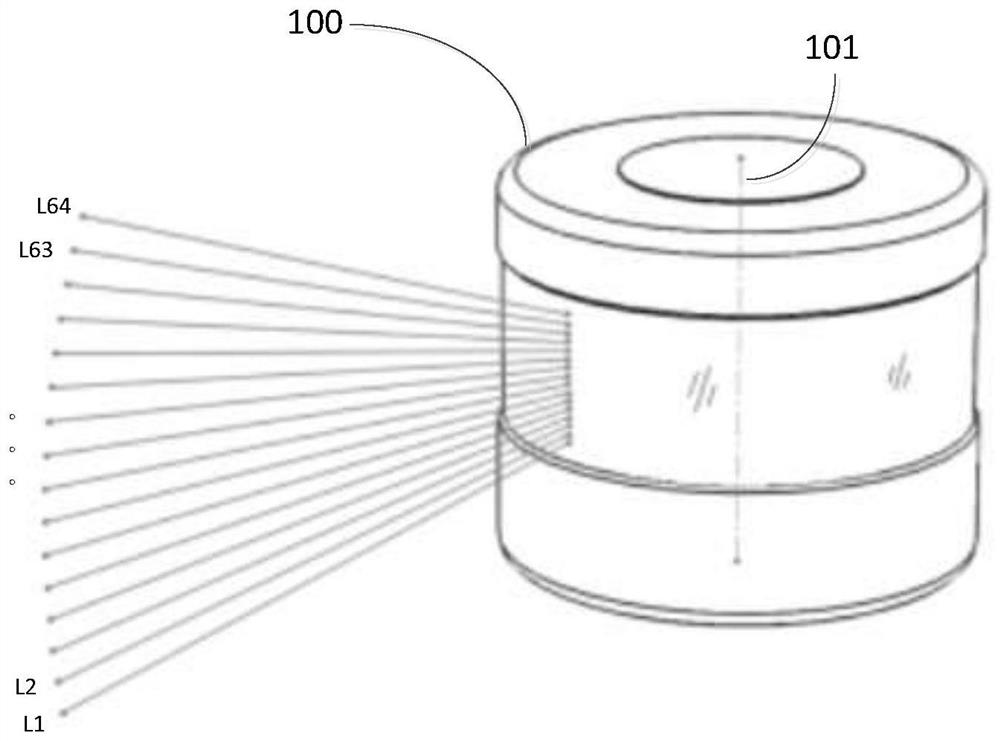
However, because the different lines of the laser radar are radiating and diverging, the closer the laser radar is, the smaller the distance between the different lines is, and even the laser spots of adjacent line beams overlap each other.
Therefore, for nearby targets, the laser beam projected on it may be too dense, and there is redundancy

Method used


Image

  • Laser radar and ranging method thereof
  • Laser radar and ranging method thereof
  • Laser radar and ranging method thereof

Examples


Embodiment Construction

[0047] In the following, only some exemplary embodiments are briefly described. As those skilled in the art would realize, the described embodiments may be modified in various different ways, all without departing from the spirit or scope of the present invention. Accordingly, the drawings and descriptions are to be regarded as illustrative in nature and not restrictive.

[0048]In describing the present invention, it is to be understood that the terms "center", "longitudinal", "transverse", "length", "width", "thickness", "upper", "lower", "front", " Back", "Left", "Right", "Vertical", "Horizontal", "Top", "Bottom", "Inner", "Outer", "Clockwise", "Counterclockwise", etc. or The positional relationship is based on the orientation or positional relationship shown in the drawings, which is only for the convenience of describing the present invention and simplifying the description, rather than indicating or implying that the referred device or element must have a specific orien...


PUM


Abstract

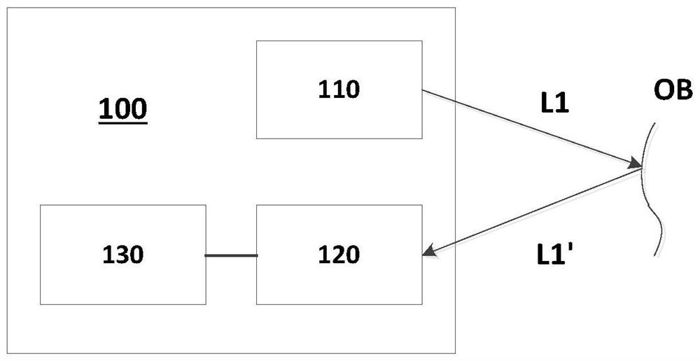
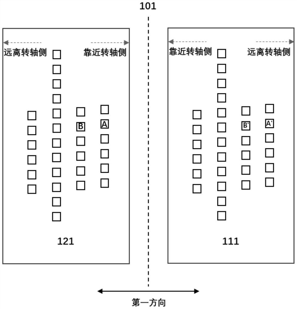
The invention provides a laser radar, comprising an emission unit which comprises a laser and can emit a plurality of laser beams for target object detection; a receiving unit which comprises a detector array and can receive reflected echoes and convert the echoes into electric signals; and a processing unit which can calculate the distance between a target object and the laser radar according to the electric signals output by the detector array, and outputs the electric signals of part of detectors in the detector array according to a preset mode when a preset condition is met. The invention further provides a method for ranging by using the laser radar. By reducing the line number on the short-distance target object, the problems that the performance of the laser radar for measuring the short-distance target object is reduced and the line number at the near position is redundant are solved. The property that the high-harness laser radar is redundant in the short distance is utilized, when the laser radar is designed, the short-distance measurement performance of part of harnesses is preferentially guaranteed, and when the distance value obtained by measuring the harnesses with poor short-distance performance is within a certain short-distance specific range, the measurement results of the harnesses are not output.

Description

technical field [0001] The present disclosure relates to the field of optoelectronic technology, and in particular to a laser radar and a method for measuring distance by using the laser radar. Background technique [0002] In some laser radars with separate transceivers, the optical axes of the receiving lens group and the transmitting lens group are not coincident (non-coaxial). This optical structure will lead to a decrease in the measurement performance of the laser radar for nearby targets. This problem can only be improved to a certain extent through various optical and other methods, and cannot be completely solved. [0003] As the number of lidar lines increases, the spatial resolution of lidar becomes higher and higher. However, since the different lines of the lidar radiate and diverge, the closer to the lidar, the smaller the distance between the different lines, and even the laser spots of adjacent line beams overlap each other. Therefore, for nearby targets, t...

Claims


Application Information

Patent Timeline
Patent Type & Authority Applications(China)
IPC IPC(8): G01S17/08G01S7/484G01S7/487G01S7/4911G01S7/4912G01S7/493
CPCG01S17/08G01S7/484G01S7/487G01S7/4911G01S7/4912G01S7/493
Inventor 梁峰王瑞向少卿
Owner HESAI TECH CO LTD
Why Eureka
Try Eureka