
A hybrid massive MIMO uplink channel estimation method

A channel estimation and estimated value technology, applied in the direction of digital transmission system, error prevention, electrical components, etc., can solve the problem of channel estimation performance degradation, achieve the effect of improving the scope of application, avoiding the problem of base mismatch, and improving accuracy

Active Publication Date: 2022-05-13
HANGZHOU DIANZI UNIV
View PDF4 Cites 0 Cited by
  • Summary
  • Abstract
  • Description
  • Claims
  • Application Information

AI Technical Summary

Problems solved by technology

When the interval between multiple frequencies of the signal is smaller than a certain threshold, the channel estimation performance will degrade

Method used


Image

  • A hybrid massive MIMO uplink channel estimation method
  • A hybrid massive MIMO uplink channel estimation method
  • A hybrid massive MIMO uplink channel estimation method

Examples


example 1

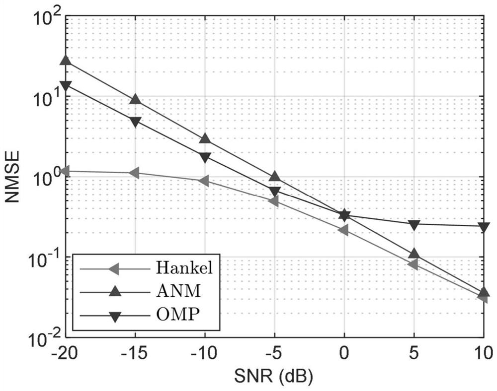
[0053] Simulation example 1: Select the number of antennas N=63, the number of radio frequency chains M=35, the antenna spacing d=λ / 2, the number of channel paths L=3, and the number of Monte Carlo experiments M c =500. The normalized mean square error was used to evaluate the estimation accuracy of the algorithm. The normalized mean square error is defined as: Among them, h es is the channel estimated by each method, and h is the real channel. The channel path gain is set as a random complex gain, and the angle of arrival of the three channel paths is AOA=(80°, 81°, 85°). The antenna at the base station adopts a uniform linear array, the signal-to-noise ratio ranges from -20dB to 10dB, and the grid density of the compressed sensing algorithm OMP is set to Δθ=2°. The algorithm proposed in the present invention is compared with the channel estimation algorithm based on the compressed sensing algorithm OMP and the atomic norm minimization algorithm ANM.

example 2

[0054] Simulation example 2: Select antenna number N=63, antenna spacing d=λ / 2, channel path number L=3, signal-to-noise ratio is 5dB, channel path gain is random complex gain, and the angle of arrival of the three channel paths is AOA= (80°, 81°, 85°), the number of RF chains varies from 30 to 60. The antenna at the base station adopts a uniform linear array, and the number of Monte Carlo experiments is M c =500. The grid density of the compressive sensing algorithm OMP is set to Δθ=2°. The algorithm proposed in the present invention is compared with the channel estimation algorithm based on the compressed sensing algorithm OMP and the atomic norm minimization algorithm ANM.

[0055] Depend on image 3 It can be seen from the normalized mean square error performance comparison diagram that under different SNR conditions, the performance of the algorithm proposed by the present invention is better than that of other algorithms, reflecting the accuracy of the proposed algori...


PUM


Abstract

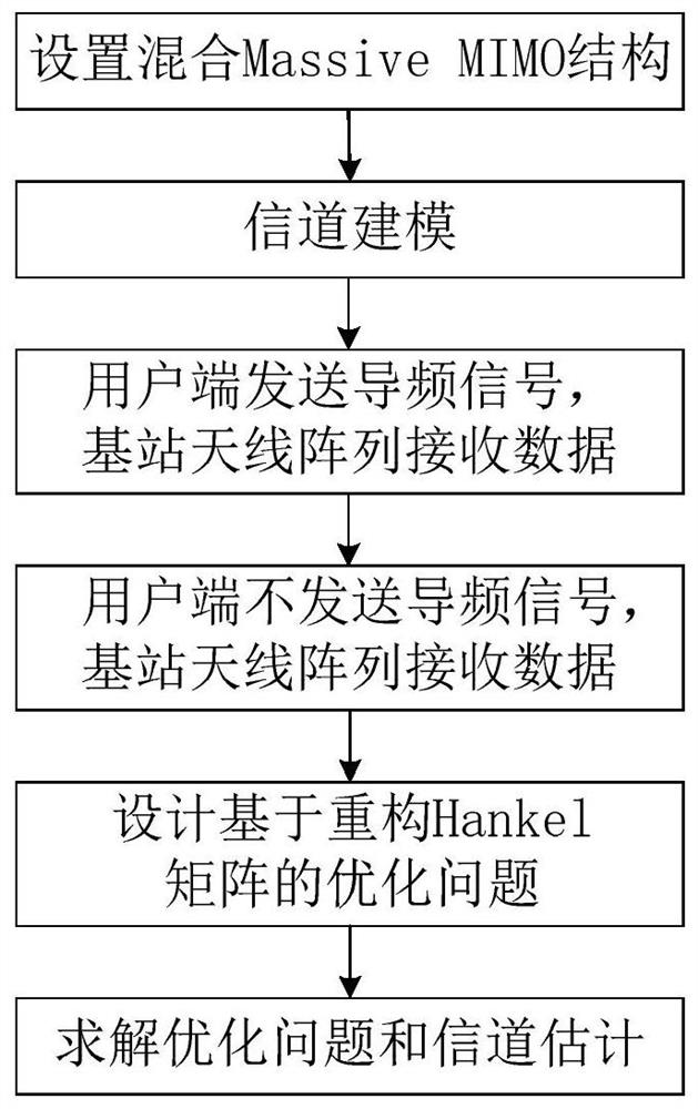
The invention discloses a hybrid Massive MIMO uplink channel estimation method. There are many limitations in traditional methods when dealing with this problem, such as the inability to estimate a single snapshot. The method of the present invention first sets up the hybrid Massive MIMO structure, and models the channel; the user end sends pilot signals, and the base station antenna array receives data to obtain sampling signals; the user end does not send pilot signals, and the base station antenna array receives noise signals; the design is based on The optimization problem of reconstructing the Hankel matrix is ​​solved to obtain the estimated value of the channel. The method of the invention can perform channel estimation only by taking a single snapshot data, and does not need to estimate the channel number, and can avoid the base mismatch problem and the signal frequency interval limitation of the traditional compressed sensing method at the same time. The method of the invention obtains the noise parameters of the base station receiver when the base station antenna array element receives data, so that the model has denoising capability and improves the accuracy of channel estimation.

Description

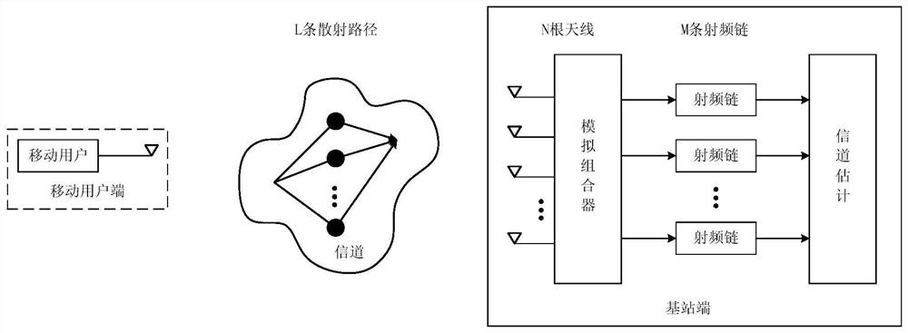
technical field [0001] The invention belongs to the technical field of wireless communication, and relates to a hybrid Massive MIMO uplink channel estimation method, in particular to a hybrid Massive MIMO uplink channel estimation method based on reconstructed Hankel matrix. Background technique [0002] Massive MIMO (Massive Multi-input Multi-output) is one of the key technologies of the 5G mobile communication system, which has the advantages of high spectral efficiency and high energy efficiency. Since the millimeter wave frequency band can provide a large bandwidth, the combination of Massive MIMO and millimeter wave has attractive application prospects. But in the traditional Massive MIMO structure, each antenna needs to be connected to a radio frequency link. Since the number of antenna elements is usually very large, the base station will need to deploy a large number of radio frequency chains, which will further increase the system hardware deployment cost and power...

Claims


Application Information

Patent Timeline
Patent Type & Authority Patents(China)
IPC IPC(8): H04B7/0452H04L1/00
CPCH04B7/0452H04L1/0048
Inventor 潘玉剑王锋
Owner HANGZHOU DIANZI UNIV
Learn More