
Industrial automatic control machine room

A computer room and industrial technology, applied in the field of industrial automatic control computer room, can solve the problems of inability to achieve automatic warning and heat dissipation.

Inactive Publication Date: 2021-09-07
邹莎
View PDF0 Cites 0 Cited by
  • Summary
  • Abstract
  • Description
  • Claims
  • Application Information

AI Technical Summary

Problems solved by technology

[0004] Aiming at the deficiencies of the existing technology, the present invention provides an industrial automatic control machine room, which can effectively solve the problem that automatic warning and heat dissipation cannot be achieved during the continuous temperature rise process inside the machine room after the cooling system inside the machine room fails.

Method used


Image

  • Industrial automatic control machine room
  • Industrial automatic control machine room
  • Industrial automatic control machine room

Examples


Embodiment Construction

[0026] The following will clearly and completely describe the technical solutions in the embodiments of the present invention in conjunction with the accompanying drawings of the present invention. Obviously, the described embodiments are only some, not all, embodiments of the present invention. Based on the embodiments of the present invention, all other embodiments obtained by persons of ordinary skill in the art without making creative efforts belong to the protection scope of the present invention.

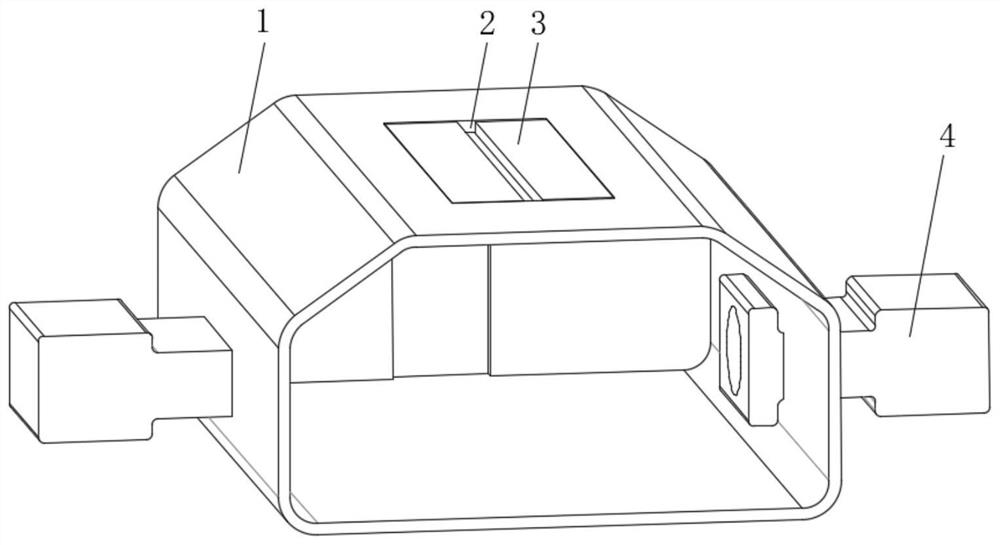
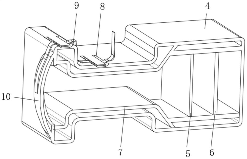
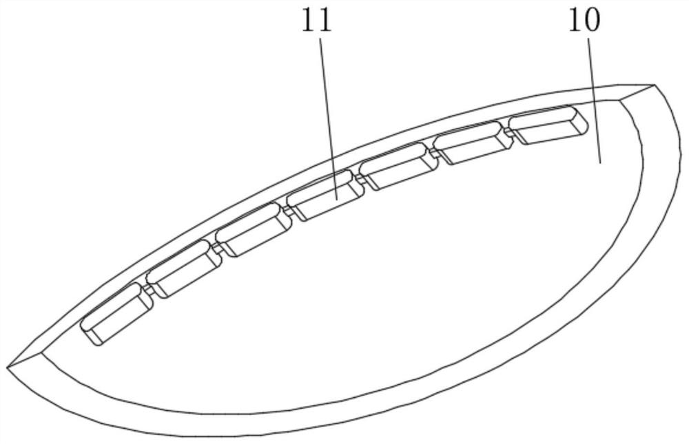
[0027] Such as Figure 1-5 As shown, an industrial automatic control machine room includes a heat insulating wall 1, a ventilation slot 2 is opened on the top of the heat insulating wall 1, a temperature sensing box 4 is installed on both sides of the heat insulating wall 1, and the inner side of the temperature sensing box 4 is installed There are a first isolation plate 5 and a second isolation plate 6, and a hollow partition 7 is installed on the inside of the temperature s...


PUM


Abstract

The invention provides an industrial automatic control machine room, and relates to the field of industrial automatic control system device manufacturing. The industrial automatic control machine room comprises a heat insulation wall, and a ventilation groove is formed in the top end of the heat insulation wall. Temperature sensing boxes are installed on the two sides of the heat insulation wall. A first isolation plate and a second isolation plate are installed on the inner side of each temperature sensing box, and a hollow partition plate is installed on the inner side of each temperature sensing box. Two sets of limiting grooves are formed in the outer side of each temperature sensing box. An elastic cover is installed at one end of each temperature sensing box, and one end of each temperature sensing box is open. A transmission rope is installed on the outer side of each elastic cover, and a plurality of sets of connecting blocks are installed on the inner side of each elastic cover. Two sets of sliding grooves are formed in the inner side of each connecting block, metal rods are installed on the inner sides of the sliding grooves, and connecting ropes are installed at one ends of the metal rods. The problem that after a cooling system in the machine room breaks down, automatic early warning and heat dissipation cannot be achieved in the continuous temperature rising process in the machine room is effectively solved.

Description

technical field [0001] The invention relates to the field of manufacturing of industrial automatic control system devices, in particular to an industrial automatic control machine room. Background technique [0002] The computer room is a place for storing servers and automatic control systems. A circulating cooling system is required inside the computer room to ensure a constant temperature inside the computer room. Generally, the computer room is left unattended. When the circulating cooling system fails and there is no early warning, the computer room will The temperature will continue to rise, causing the internal devices to burn out due to the high temperature. Contents of the invention [0003] (1) Solved technical problems [0004] Aiming at the deficiencies of the prior art, the present invention provides an industrial automatic control machine room, which can effectively solve the problem that automatic early warning and heat dissipation cannot be achieved during...

Claims


Application Information

Patent Timeline
Patent Type & Authority Applications(China)
IPC IPC(8): H05K7/20G08B3/14
CPCH05K7/20709H05K7/20745G08B3/14
Inventor 邹莎
Owner 邹莎
Learn More