Portable sample display device and use method thereof
A portable and sample technology, applied in display stands, display hangers, display shelves, etc., can solve the problems of high risk, inconvenient, time-consuming and laborious
- Summary
- Abstract
- Description
- Claims
- Application Information
AI Technical Summary
Problems solved by technology
Method used
Image
Examples
Embodiment 1
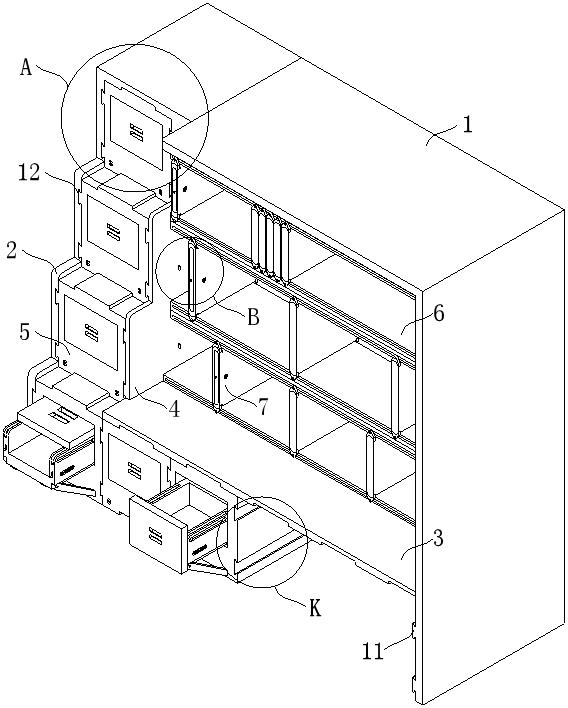
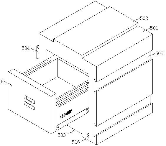
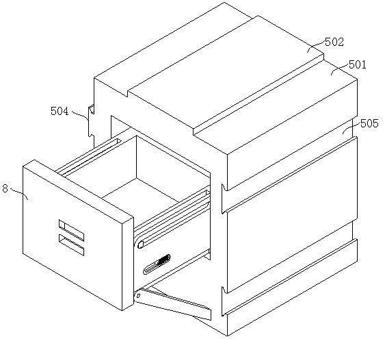
[0060] Such as figure 1 , figure 2 , Figure 5 , Figure 12As shown, this embodiment proposes a portable device for displaying samples, including a frame 1, a partition 4 is fixed on one side of the bottom of the frame 1, a fixed plate 3 is fixed on the bottom of the partition 4, and one side of the fixed plate 3 is connected to the bottom of the frame 1. The inner wall of the frame 1 is fixedly connected, the rear end of the frame 1 is fixed with a guard plate, the top of the frame 1 is fixed with a top plate on the side of the partition 4, and the bottom of the top plate is fixed with a support plate on the side away from the partition 4 2. The support plate 2 is provided with several No. 2 dovetail slots 12 on the side close to the partition 4, and the partition 4 is provided with several No. 2 dovetail slots corresponding to the positions of the No. 2 dovetail slots 12 on the side close to the support plate 2. Block 11, No. 2 dovetail groove 12 and No. 2 dovetail block...
Embodiment 2
[0062] The scheme in embodiment 1 is further introduced below in combination with specific working methods, see the following description for details:
[0063] Such as figure 1 , Figure 12 , Figure 13 As shown, as a preferred embodiment, on the basis of the above method, further, the placement mechanism includes a load-bearing mechanism and a positioning mechanism 7, and the load-bearing mechanism includes several sets of limit components arranged on the inner side of the frame 1, each set The limit assembly is composed of two horizontal plates 6, each horizontal plate 6 is fixedly connected with the inner wall of the frame 1 and the inside of the partition plate 4, and the rear end of each horizontal plate 6 is provided with a No. 2 sliding groove 14, and the No. 2 sliding groove 14 Use the position adjustment mechanism 7 to slide left and right, and arrange the space reasonably according to the size of the sample.
[0064] Such as figure 1 , Figure 9 , Figure 11 , ...
Embodiment 3
[0072] The schemes in Embodiment 1 and Embodiment 2 are further introduced below in conjunction with specific working methods, see the following description for details:
[0073] A method for using a portable device for displaying samples, comprising the following steps:
[0074] S1a: When steps are needed, take out the assembly mechanism 5 under the fixed plate 3, and then align the assembly mechanism 5 between the support plate 2 and the partition 4 with the No. 1 dovetail groove 505 and the No. Align the dovetail slot 12 with the No. 1 dovetail block 504, and the positioning block 502 with the No. 1 positioning slot 503 for assembly. After assembling, hold the handle 803 in the deformed structure and pull out the storage mechanism 8. After pulling out, use both hands Press and hold the push block 901 and pull it to the front, the baffle 802 will be released, then let go and slide the baffle 802 to the top of the two side plates 811, and turn the support rod 1001 clockwise b...
PUM
 Abstract
Description
Claims
Application Information
 - R&D
- Intellectual Property
- Life Sciences
- Materials
- Tech Scout
- Unparalleled Data Quality
- Higher Quality Content
- 60% Fewer Hallucinations
Browse by: Latest US Patents, China's latest patents, Technical Efficacy Thesaurus, Application Domain, Technology Topic, Popular Technical Reports.
© 2025 PatSnap. All rights reserved.Legal|Privacy policy|Modern Slavery Act Transparency Statement|Sitemap|About US| Contact US: help@patsnap.com


