Cutter shaft of crusher and film crushing processing method

A technology of crusher and cutter shaft, which is applied in the direction of mechanical material recycling, grain processing, plastic recycling, etc., can solve the problems of material jam, low efficiency and low efficiency.

Active Publication Date: 2021-09-10
江门市德泓装备技术有限公司
View PDF7 Cites 1 Cited by
  • Summary
  • Abstract
  • Description
  • Claims
  • Application Information

AI Technical Summary

Problems solved by technology

[0006] Second, because there will be a gap between the moving knife and the fixed knife, the oblique installation of the straight knife will cause the material to jam or the efficiency will be reduced due to the enlarged gap, because the material will follow the scissors-like shearing action of the blade during the crushing process. , the material will slip axially, and eventually accumulate in the gap between the end face of the moving knife and the end face of the fixed flange of the frame, causing material jams. Another treatment method is to enlarge the gap between the moving knife and the end baffle, resulting in low efficiency

Method used


Image

  • Cutter shaft of crusher and film crushing processing method
  • Cutter shaft of crusher and film crushing processing method
  • Cutter shaft of crusher and film crushing processing method

Examples


Embodiment Construction

[0033] Below in conjunction with accompanying drawing and embodiment the present invention is described in detail:

[0034] In order to deepen the understanding of the present invention, the present invention will be further described in detail below in conjunction with examples of implementation and accompanying drawings. The present invention can be implemented in the following ways:

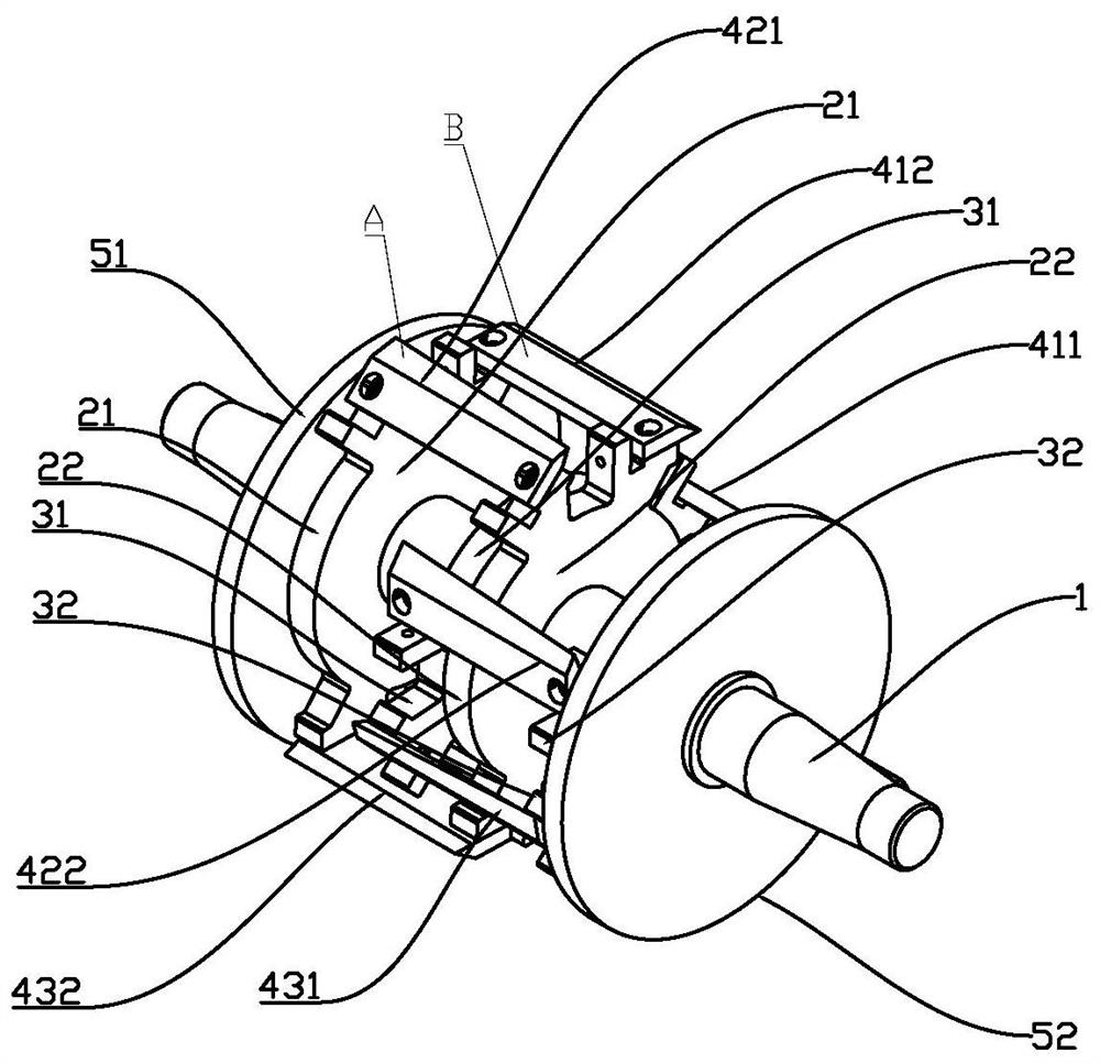
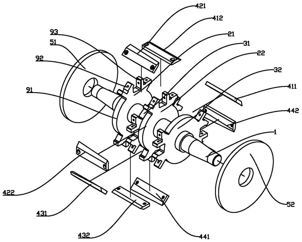
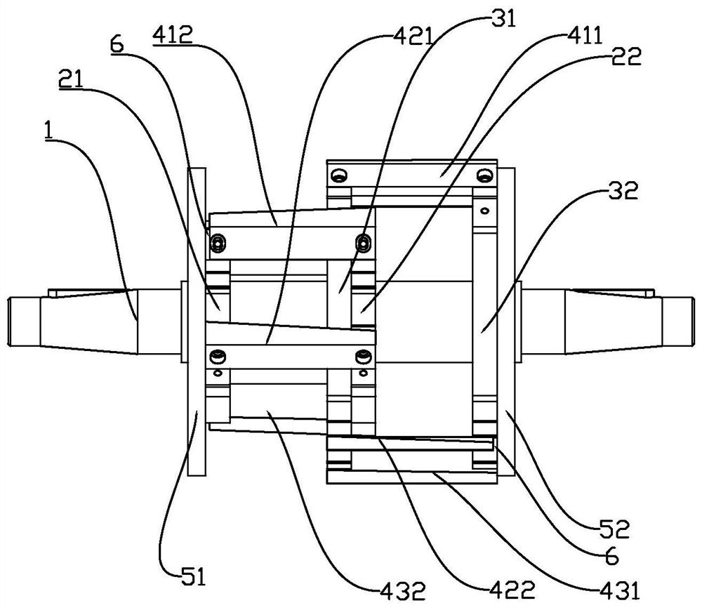
[0035] A cutter shaft of a crusher includes a main shaft 1 on which a front end baffle 51 and a rear end baffle 52 are arranged and correspondingly arranged at both ends of the main shaft 1 . On the main shaft 1, between the front end face baffle plate 51 and the rear end face baffle plate 52, the front one tool rest 21, the rear one tool rest 31, the front two tool rests 22 and the rear two tool rests 32 are arranged respectively in sequence. Such as figure 1 , 2 As shown, the rear one tool rest 31 and the front two tool rests 22 are overlapped and arranged in the middle of the main shaft ...


PUM


Abstract

The invention relates to a cutter shaft of a crusher. The cutter shaft comprises a main shaft, wherein a front end face baffle plate and a rear end face baffle plate are arranged on the main shaft and are correspondingly arranged at two ends of the main shaft. A first front tool rest, a first rear tool rest, a second front tool rest and a second rear tool rest are sequentially arranged between the front end face baffle plate and the rear end face baffle plate on the main shaft. The first rear knife rest and the second front knife rest are arranged in the middle of the main shaft in an overlapped mode, and the first front knife rest and the second front knife rest are sequentially provided with a special-shaped knife A, a special-shaped knife B, a special-shaped knife A and a special-shaped knife B in the circumferential direction. According to the scheme, through the arrangement method of axial overlapping and tangential dislocation of the knife rest set, namely the arrangement mode of the first front knife rest, the first rear knife rest, the second front knife rest and the second rear knife rest, the special-shaped knife A and the special-shaped knife B which are arranged on the first front knife rest and the second front knife rest are partially crossed and overlapped with the special-shaped knife A and the special-shaped knife B which are arranged on the first rear knife rest and the second rear knife rest, so that axial clearances between cutters in the same group can be avoided, and the cutting efficiency is improved. The cutting effect is good, the instant impact in the cutting process is lower, the vibration is smaller, the service life of equipment can be effectively prolonged, the noise is lower, and the noise pollution of the equipment is reduced.

Description

【Technical field】 [0001] The invention relates to a crusher cutter shaft applied to a film crusher and a film crushing method. 【Background technique】 [0002] At present, the common film crusher in the market is driven by the motor to rotate the moving knife, and the film entering the feed port is driven by the inertial force, and has a cutting effect with the fixed knife, so that the film can be crushed and reused. This is the case for example in the following three published patents. For example, patent No. 201120138314X, named as a rotary cutter for a film crusher, announced on 2011.11.30. 2011201480385, named as a rotary cutter for a film crusher, announced on 2011.11.23. Patent No. 2014202379198, the name is a film shredder, and the announcement date is 2014.09.10. [0003] The moving knife is composed of a main shaft, a knife holder and multiple sets of blades. The blade is straight and inclined, and the blade is straight. The blade is installed at a certain angle w...

Claims


Application Information

Patent Timeline
Patent Type & Authority Applications(China)
IPC IPC(8): B02C18/16B02C18/18B02C18/14
CPCB02C18/18B02C18/16B02C18/14Y02W30/52
Inventor 石卫卫李景曦杨虎
Owner 江门市德泓装备技术有限公司
Why Eureka
Try Eureka