Efficient cutter shaft applied to film crusher and crusher with efficient cutter shaft

A crusher, high-efficiency technology, applied in grain processing and other directions, which can solve problems such as low efficiency, material jamming, and reduced efficiency

Active Publication Date: 2021-09-10
江门市德泓装备技术有限公司
View PDF3 Cites 1 Cited by
  • Summary
  • Abstract
  • Description
  • Claims
  • Application Information

AI Technical Summary

Problems solved by technology

[0006] Second, because there will be a gap between the moving knife and the fixed knife, the oblique installation of the straight knife will cause the material to jam or the efficiency will be reduced due to the enlarged gap, because the material will follow the scissors-like shearing action of the blade during the crushing process. , the material will slip axially, and eventually accumulate in the gap between the end face of the moving knife and the end face of the fixed flange of the frame, causing material jams. Another treatment method is to enlarge the gap between the moving knife and the end baffle, resulting in low efficiency

Method used


Image

  • Efficient cutter shaft applied to film crusher and crusher with efficient cutter shaft
  • Efficient cutter shaft applied to film crusher and crusher with efficient cutter shaft
  • Efficient cutter shaft applied to film crusher and crusher with efficient cutter shaft

Examples


Embodiment Construction

[0032] Below in conjunction with accompanying drawing and embodiment the present invention is described in detail:

[0033] In order to deepen the understanding of the present invention, the present invention will be further described in detail below in conjunction with examples of implementation and accompanying drawings. The present invention can be implemented in the following ways:

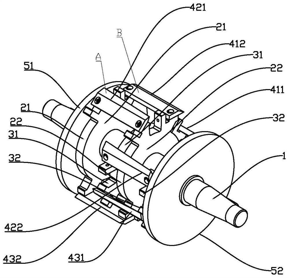
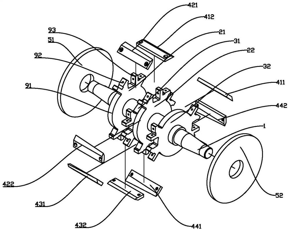
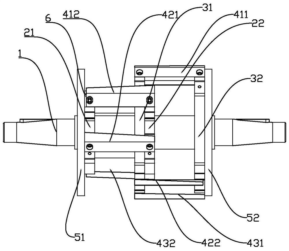
[0034] The cutter shaft in this case includes a rotating spindle, a cutter holder, an end face baffle and a special-shaped cutter. Among them, the main shaft is the main carrier of the special-shaped cutter, which is segmented in order in the axial direction, as follows: the input flywheel installation section, the bearing installation section, the working section, the bearing installation section, and the counterweight flywheel installation section, so that it forms a complete cutter shaft . While ensuring the workload, only two rows of knives are installed in the axial direction between th...


PUM


Abstract

The invention relates to an efficient cutter shaft applied to a film crusher and the crusher with the efficient cutter shaft. The efficient cutter shaft comprises a main shaft, cutter rests and baffles. The baffles are divided into a front end face baffle and a rear end face baffle and are correspondingly arranged at the two ends of the main shaft. A front cutter rest set and a rear cutter rest set are arranged between the front end face baffle and the rear end face baffle. The front cutter rest set and the rear cutter rest set are each provided with a plurality of special-shaped cutters. Cutting edges of the special-shaped cutters incline from high to low from one end to the other end. According to the scheme, for gaps between fixed cutters and movable cutters of domestic film crushers, the cutting edges of the special-shaped cutters can be absolutely matched with the cylindrical faces of the cutting edges of the fixed cutters in theory; and the machining precision problem of special-shaped servo grinding is considered, the width of a working section of the main shaft is shortened, the entity deviation of the cutting edges of the movable cutters can be effectively controlled, and the gaps between the cutting edges of the movable cutters and the cutting edges of the fixed cutters are effectively controlled. In this way, the problem that the gaps exist between the movable cutters and the fixed cutters is solved. The cutting effect is good, the instant impact in the cutting process is lower, vibration is smaller, the service life of equipment can be effectively prolonged, noise is lower, and noise pollution of the equipment is reduced.

Description

【Technical field】 [0001] The invention relates to a high-efficiency cutter shaft applied to a film crusher and the crusher thereof. 【Background technique】 [0002] At present, the common film crushers in the market are driven by a motor to rotate the moving knife, and the uniform cutting knives are all straight knives. Driven by the inertial force, the film entering the feeding port will have a cutting effect with the fixed knife, so that the film can be crushed and reused. This is the case for example in the following three published patents. Patent No. 201120138314X, named as a rotary cutter for a film crusher, announced on 2011.11.30. 2011201480385, named as a rotary cutter for a film crusher, announced on 2011.11.23. Patent No. 2014202379198, the name is a film shredder, and the announcement date is 2014.09.10. [0003] The moving knife is composed of a main shaft, a knife holder and multiple sets of blades. The blade is straight and inclined, and the blade is straig...

Claims


Application Information

Patent Timeline
IPC IPC(8): B02C18/18B02C18/16B02C18/14
CPCB02C18/18B02C18/16B02C18/14
Inventor 石卫卫李景曦杨虎
Owner 江门市德泓装备技术有限公司
Why Eureka
Try Eureka