Shaft coupling of mechanical supercharger

A technology of mechanical superchargers and couplings, applied in couplings, elastic couplings, mechanical equipment, etc., can solve the problem of shortening the fatigue life of coupling torque springs, and solve the grooves on the inner surface of the torque springs. Influence of notches, effect of reducing wear, avoiding stress concentration

Inactive Publication Date: 2010-11-10
JAPHL POWERTRAIN SYST
View PDF4 Cites 3 Cited by
  • Summary
  • Abstract
  • Description
  • Claims
  • Application Information

AI Technical Summary

Problems solved by technology

The formation of this groove will cause the stress concentration of the torsion spring here, further shortening the fatigue life of the coupling torsion spring

Method used


Image

  • Shaft coupling of mechanical supercharger
  • Shaft coupling of mechanical supercharger
  • Shaft coupling of mechanical supercharger

Examples


Embodiment Construction

[0033] In the following, referring to the accompanying drawings, through the description of the embodiments, the specific embodiments of the present invention, such as the shape and structure of each component involved, the mutual position and connection relationship between each part, the function and working principle of each part, etc. will be further described. Details of:

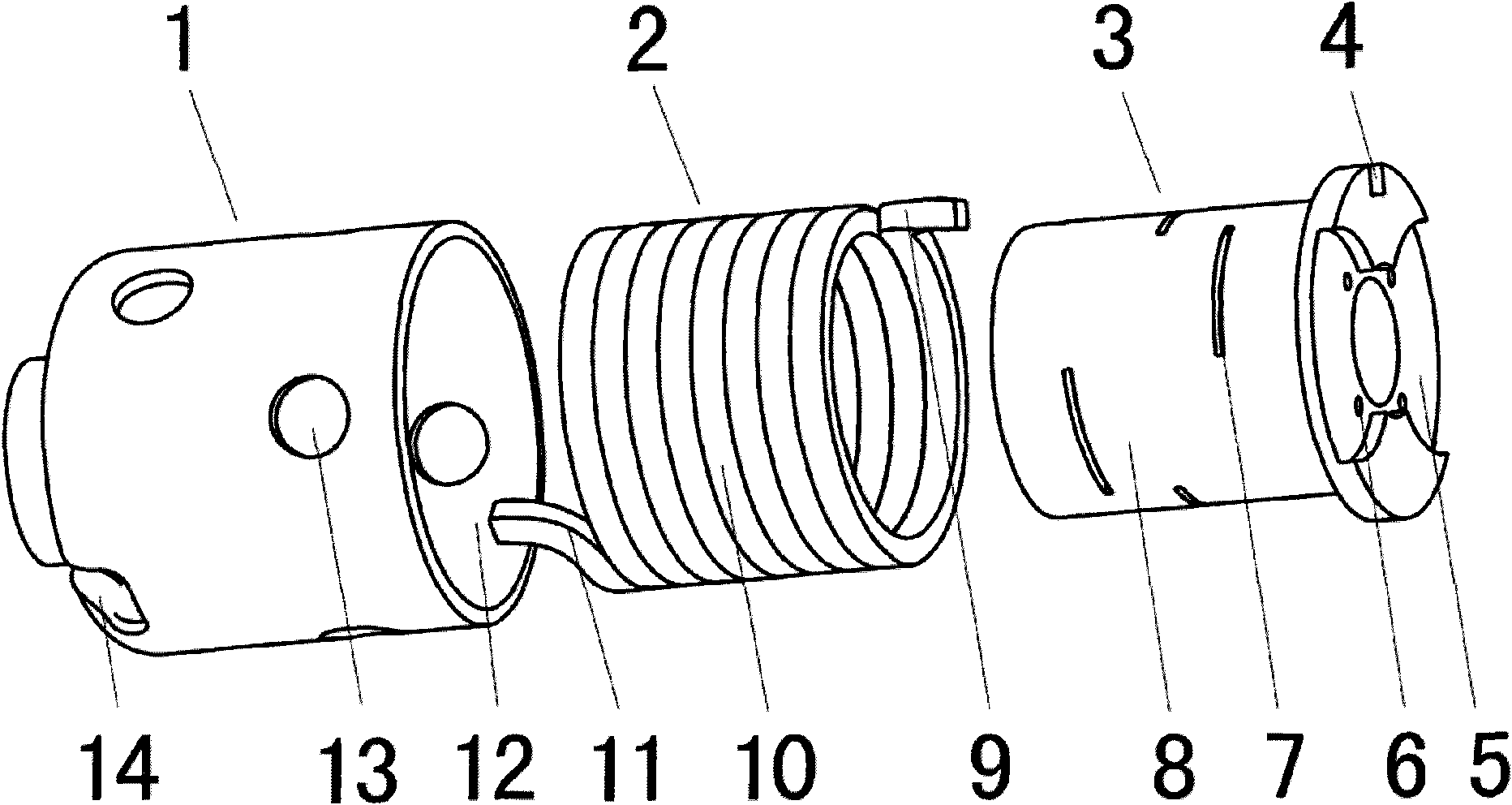
[0034] as attached figure 1 As shown, the present invention is a coupling of a supercharger, and the coupling of the supercharger includes a front hub 1, a torsion spring 2, a rear hub 3, a rear notch 4, and a rear tang 9. , the front tang 11, the front slot 14, the front hub 1 is set to a columnar cavity structure, the rear hub 3 is set to a columnar structure, the annular torsion spring 2 is set outside the rear wheel hub 3, and the rear wheel hub 3 is set in the In the front hub 1 , the front tang 11 of the torque spring 2 is clamped on the front notch 14 on the front hub 1 , and the rear tang 9 o...


PUM


Abstract

The invention provides a shaft coupling of a mechanical supercharger, which is applied to the field of mechanical superchargers. The shaft coupling of the mechanical supercharger comprises a front wheel hub (1), a torque spring (2), a back wheel hub (3), a back notch (4), a back handle leg (9), a front handle leg (11) and a front notch (14), wherein the front wheel hub (1) is arranged into a cylindrical hollow cavity structure, the back wheel hub (3) is arranged into a cylindrical structure, the annular torque spring (2) is sleeved and installed outside the back wheel hub (3), the back wheel hub (3) is sleeved and installed in the front wheel hub (1), the front handle leg (11) of the torque spring (2) is clamped on the front notch (14) on the front wheel hub (1), and the back handle leg (9) of the torque spring (2) is clamped on the back notch (4) on the back wheel hub (3). By adopting the technical scheme, mechanical noise under a pulsating load can be effectively decreased, and the abrasion of the inner surface of the torque spring and the corresponding positions of the wheel hubs can be effectively decreased.

Description

technical field [0001] The present invention relates to the field of mechanical superchargers, and more specifically, the present invention relates to a coupling of a mechanical supercharger. Background technique [0002] In the field of engines, superchargers are generally used to improve the power of the engine and reduce the emission of harmful substances. In the existing supercharger, there are a pair of intermeshing vane rotors, and the non-meshing vanes of the two rotors respectively form a control volume with the casing, and the purpose of transmitting air is achieved by the continuous replacement of the control volume. As long as the amount of air delivered to the intake manifold is greater than the instantaneous engine displacement, the intake pressure can be increased, ultimately increasing the power density of the engine. [0003] figure 2 It is a schematic diagram of the power transmission and air transmission between the existing supercharger and the engine (s...

Claims


Application Information

Patent Timeline
Patent Type & Authority Applications(China)
IPC IPC(8): F16D3/52F16H57/04
Inventor 段凯磊施法佳项青新范礼
Owner JAPHL POWERTRAIN SYST
Why Eureka
Try Eureka