Manufacturing method for double-screw-rod compressor rotor

A compressor rotor and twin-screw technology, applied in the field of compressor manufacturing, can solve problems such as synchronous gear power loss, polymer material aging, material erosion, etc., to reduce energy consumption and vibration and noise levels, and to achieve good water film sealing and lubrication Conditions, the effect of reducing leakage in the compression chamber

Inactive Publication Date: 2017-12-08
SUZHOU ALRBETTER PRECISION MACHINERY
View PDF5 Cites 9 Cited by
  • Summary
  • Abstract
  • Description
  • Claims
  • Application Information

AI Technical Summary

Problems solved by technology

Disadvantages of water-lubricated rotors: ①Due to the low boiling point of water, water-lubricated rotors cannot be used in high-temperature environments; ②Water, especially seawater, has a strong corrosion effect, and the conductivity of pure water is hundreds of millions or even hundreds of millions higher than ordinary lubricating oil It can cause the electrochemical corrosion of most metal materials and the aging of polymer materials; ③The high vaporization pressure of water is easy to produce cavitation, which makes the material eroded
[0007] To sum up, the rotors of water-lubricated twin-screw compressors under the current technical level mainly work with stainless steel rotors and synchronous gears. The working chamber of the rotor and the bearing chamber are separated by mechanical seals. The main problem is that Ensure that the rotors do not come into contact. The meshing gap between the rotors is too large, so that the volumetric efficiency of the compressor is low.
Another problem existing in the prior art is that the maintenance of the mechanical seal is troublesome, coupled with a series of problems such as the power loss of the synchronous gear, and the regular maintenance of the lubricating oil system, there is an urgent need for a new screw rotor preparation method to solve the above problems

Method used


Image

  • Manufacturing method for double-screw-rod compressor rotor
  • Manufacturing method for double-screw-rod compressor rotor
  • Manufacturing method for double-screw-rod compressor rotor

Examples


Embodiment Construction

[0028] The present invention will be further described below in conjunction with the accompanying drawings and specific embodiments.

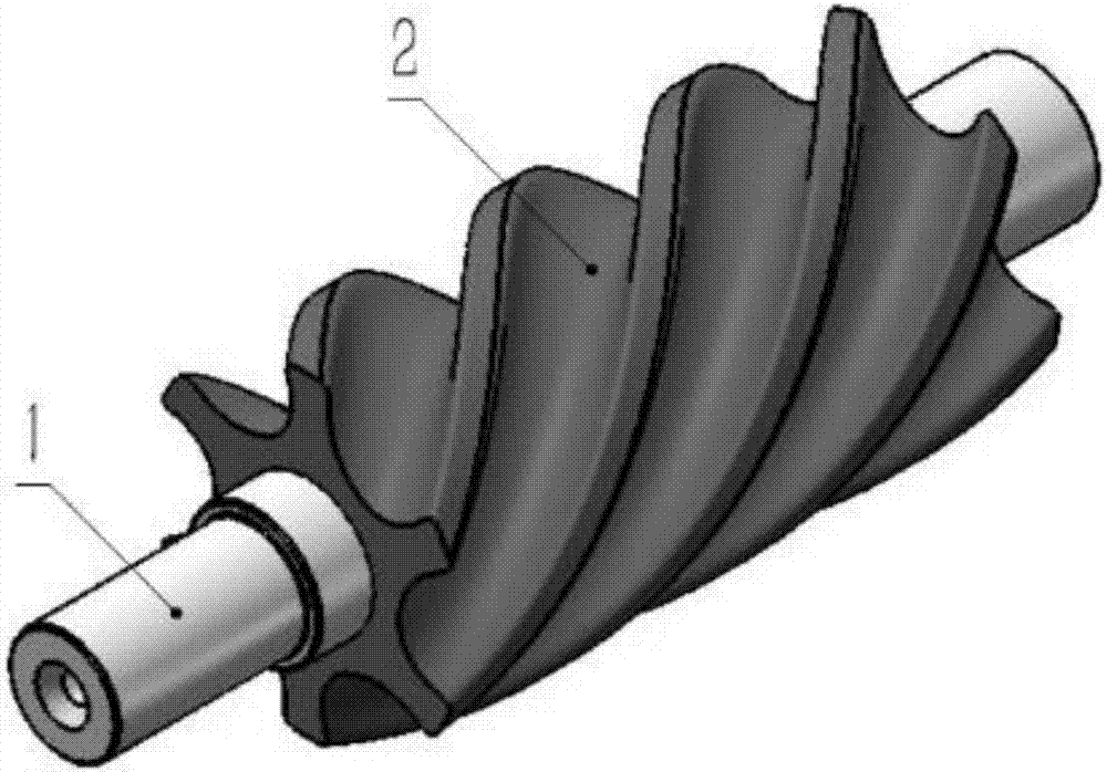
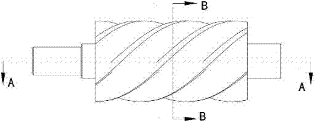
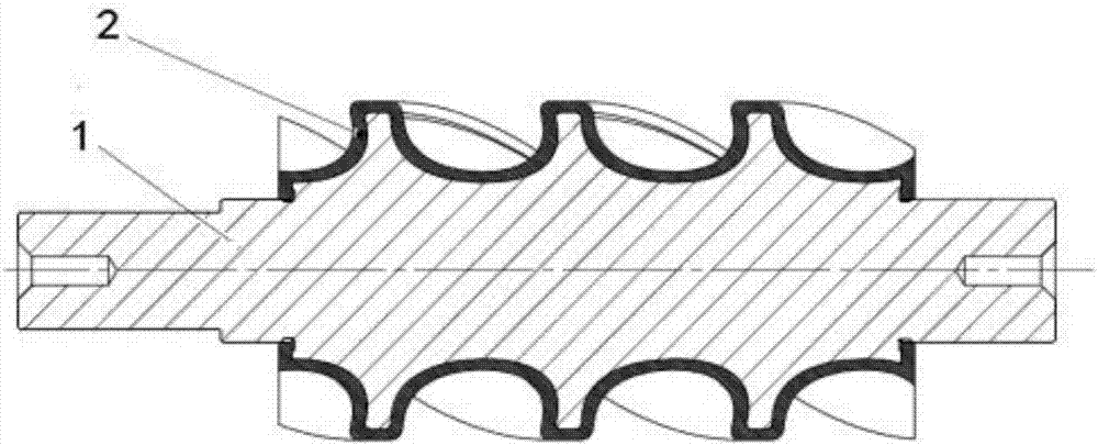
[0029] A method for preparing a rotor of a twin-screw compressor, which includes a female rotor stainless steel core 1, a female rotor PEEK engineering plastic tooth-shaped shell 2, a female rotor end face circular pit 3, a male rotor stainless steel core 4, and a male rotor PEEK engineering plastic tooth shape The shell 5 and the circular pit 6 on the end face of the male rotor, the stainless steel core 1 of the female rotor and the PEEK engineering plastic toothed shell 2 of the female rotor are combined together by high temperature molding process.

[0030] figure 1 This is the structural diagram of the female rotor manufactured by this preparation method. The female rotor is mainly composed of the female rotor stainless steel core 1 and the female rotor PEEK engineering plastic tooth-shaped shell 2 through high-temperature molding process. ...


PUM

PropertyMeasurementUnit
thicknessaaaaaaaaaa

Abstract

The invention discloses a manufacturing method for a double-screw-rod compressor rotor. A screw-rod compressor rotor is formed by a stainless steel rotor core and a PEEK engineering plastic tooth-shaped shell through high-temperature mold pressing. In order to make an oil-free screw rod compressor reach the higher exhaust pressure (the gage pressure of 1.3 MPa) and guarantee the long-time operating reliability of the rotor, a screw rod rotor structure is made of the stainless steel rotor core and a special modified PEEK material which is 1-5 mm thick and die-cast to the surface; finally, the die-cast PEEK surface is finished in place by a form milling cutter; and to increase the bonding degree of the PEEK engineering plastic and the stainless steel rotor core, some regular circular pits are machined in the two tooth-shaped end faces of the stainless steel rotor. By the adoption of the manufacturing method, the manufacturing difficulty of the oil-free screw rod compressor rotor can be lowered greatly, the structure manner of an oil-free air screw rod compressor, an oil-free process screw rod compressor and a refrigeration screw rod compressor can be simplified, and finally the service life of the screw rod compressors can be prolonged, and the maintenance cost is lowered.

Description

technical field [0001] The invention relates to the field of compressor manufacturing, in particular to a method for preparing a twin-screw compressor rotor. Background technique [0002] Through the analysis of the life cycle cost of the compressor, it is concluded that about 80% of the life cycle cost of the compressor is the operating electricity fee, and 99% of the carbon dioxide emission also occurs during the operation. According to the U.S. Department of Energy, air compressors are among the most power-hungry devices in industry in the U.S. Although the US Department of Energy once considered electric motors to be the largest consumers of electricity, energy savings from improved compressed air system design and operation far outweigh savings from improved motor efficiency. By improving the design and operation of the compressed air system, energy can be saved by 20% to 50%. In China, 96% of the energy consumption of the compressed air system is the power consumptio...

Claims


Application Information

Patent Timeline
Patent Type & Authority Applications(China)
IPC IPC(8): F04C18/16F04C29/00B29D15/00
CPCF04C18/16B29D15/00F04C18/084F04C2230/20F04C2240/20
Inventor 李星星陈文卿邢子文
Owner SUZHOU ALRBETTER PRECISION MACHINERY
Why Eureka
Try Eureka