Steering drive device for caterpillar vehicle
A driving device and vehicle technology, applied in the direction of non-deflectable wheel steering, steering mechanism, vehicle components, etc., can solve the problems of prolonged construction time, unreasonable planetary transmission, increased meshing force of steering transmission gears, etc., to reduce power loss and Engineering cost, good stability and versatility, and the effect of reducing gear meshing force
- Summary
- Abstract
- Description
- Claims
- Application Information
AI Technical Summary
Problems solved by technology
Method used
Image

Examples
Embodiment 1
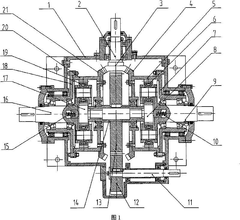
[0018] In Fig. 1, the steering drive device of the tracked vehicle of the present embodiment consists of a casing 1, a steering control input shaft 2, a steering bevel gear 3, a right bevel gear 4, a right ring gear 5, a right planetary gear 6, and a right bushing 7 , right sun gear 8, right output shaft 9, right positioner 10, power input shaft 11, pinion gear 12, large gear 13, shaft 14, left positioner 15, left output shaft 16, left sun gear 17, left bushing 18. The left planetary gear 19, the left ring gear 20, and the left bevel gear 21 are connected to form.
[0019] A power input shaft 11 is installed under the inside of the box body 1, and two bearings are installed between the power input shaft 11 and the box body 1. The left end of the power input shaft 11 is fixedly connected with a pinion 12 with a key coupling, and a large gear 13 and The pinion 12 meshes, and the bull gear 13 and the pinion 12 are cylindrical gears. The bull gear 13 and the pinion 12 spur gears o...
Embodiment 2
[0023] In this embodiment, three left planetary gears 19 are installed in the left ring gear 20 of the left planetary gear train. Three right planetary gears 6 are installed in the right ring gear 5 of the gear train, and the connection relationship between the right planetary gears 6 , the right ring gear 5 and the right output shaft 9 is the same as in Embodiment 1. Other components and the coupling relationship of the components are the same as in Embodiment 1.
Embodiment 3
[0025] In this embodiment, two left planetary gears 19 are installed in the left ring gear 20 of the left planetary gear train, and the coupling relationship between the left planetary gear 19, the left ring gear 20 and the left output shaft 16 is the same as in Embodiment 1; Two right planetary gears 6 are installed in the right ring gear 5 of the gear train, and the connection relationship between the right planetary gear 6 , the right ring gear 5 and the right output shaft 9 is the same as that of Embodiment 1. Other components and the coupling relationship of the components are the same as in Embodiment 1.
[0026] The working principle of the present invention is as follows:
[0027] 1. Tracked vehicles drive straight ahead
[0028] The steering control input shaft 2 does not rotate, the steering bevel gear 3 installed on the steering control input shaft 2 does not rotate, the left bevel gear 21 and the right bevel gear 4 meshed with the steering bevel gear 3 do not rota...
PUM
 Abstract
Description
Claims
Application Information
 - R&D
- Intellectual Property
- Life Sciences
- Materials
- Tech Scout
- Unparalleled Data Quality
- Higher Quality Content
- 60% Fewer Hallucinations
Browse by: Latest US Patents, China's latest patents, Technical Efficacy Thesaurus, Application Domain, Technology Topic, Popular Technical Reports.
© 2025 PatSnap. All rights reserved.Legal|Privacy policy|Modern Slavery Act Transparency Statement|Sitemap|About US| Contact US: help@patsnap.com