
Milling cutter placing device with positioning storage and shockproof functions

A technology of placing devices and milling cutters, applied in tool storage devices, manufacturing tools, springs/shock absorbers, etc., can solve problems such as time-consuming and labor-intensive

Pending Publication Date: 2021-09-10
常州肯达工具有限公司
View PDF0 Cites 0 Cited by
  • Summary
  • Abstract
  • Description
  • Claims
  • Application Information

AI Technical Summary

Problems solved by technology

[0004] The object of the present invention is to aim at the defects and deficiencies of the prior art, to provide a placement device for milling cutters with positioning storage and anti-shock function, which not only has anti-shock function, but also facilitates classification and placement according to size, which is convenient Quickly take and use, avoiding time-consuming and labor-intensive problems caused by manual placement

Method used


Image

  • Milling cutter placing device with positioning storage and shockproof functions
  • Milling cutter placing device with positioning storage and shockproof functions
  • Milling cutter placing device with positioning storage and shockproof functions

Examples


Embodiment Construction

[0023] The technical solution in the present invention will be clearly and completely described below in conjunction with the accompanying drawings. The preferred embodiment in the description is only used as an example, and all other embodiments obtained by those skilled in the art without making creative work, All belong to the protection scope of the present invention.

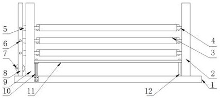
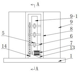
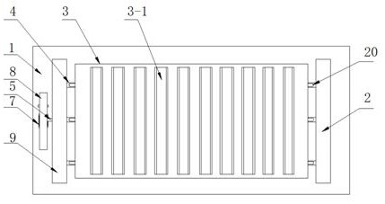
[0024] Such as Figure 1-Figure 7 As shown, the specific embodiment adopts the following technical scheme: it includes a bottom plate 1, a right side plate 2, a sieve plate 3, a cam 5, a driving motor 7, a gear frame 8, a left side plate 9, an electric telescopic rod 10, a pressing plate 11, Buffer spring 17 and elastic extrusion body 21; the upper part of bottom plate 1 is welded and fixed with left side plate 9 and right side plate 2 symmetrically, and three sieve plates 3 are arranged on left side plate 9 and right side plate in sequence from top to bottom. 2; the inner wall of the right side plate 2 is...


PUM


Abstract

The invention discloses a milling cutter placing device with positioning storage and shockproof functions, and relates to the technical field of hardware storage. A plurality of groove bodies corresponding to a sieve plate are formed in the inner wall of a right side plate, and a buffer spring is embedded in each groove body; and hooks arranged in an inverted-L-shaped structure are fixed to the left side and the right side of the sieve plate, the hooks are movably hooked to guide shafts, the guide shafts are movably arranged in guide bearings in a penetrating manner, and the guide bearings connected with the guide shafts on the left side and the right side in a matched and guiding manner are embedded in the left side plate and the right side plate respectively. The outer end of each guide shaft on the right side is fixedly connected with the corresponding buffer spring. The outer end of each guide shaft on the left side is in movable contact with the outer edge of a cam. According to the invention, the anti-vibration effect is achieved, meanwhile, classified placement according to the size is facilitated, taking and using are convenient to carry out, and the problem of time and labor consumption caused by manual placement is avoided.

Description

technical field [0001] The invention relates to the technical field of hardware storage, in particular to a placement device for milling cutters with positioning storage and shockproof functions. Background technique [0002] A milling cutter is a rotating tool with one or more teeth for milling operations. When working, each knife tooth cuts off the allowance of the workpiece intermittently in turn. Milling cutters are mainly used for machining planes, steps, grooves, forming surfaces and cutting off workpieces on milling machines. [0003] The current milling cutter placement device is generally manually placed one by one, which is not only inefficient, but also inconvenient to classify and place according to size, and it is not convenient to take and use later; at the same time, the existing placement device basically adopts an upright storage box , Place the milling cutter in the upright storage box. During the movement, there will be collision between the milling cutt...

Claims


Application Information

Patent Timeline
IPC IPC(8): B25H3/00B07B1/12F16F15/02F16F15/067
CPCB25H3/00B07B1/12F16F15/02F16F15/067
Inventor 江禹轩恽克勤徐祥包文峰巢红星
Owner 常州肯达工具有限公司
Learn More