Anchorage device

A technology of anchors and anchor rings, which is applied in the processing of building materials, structural elements, building components, etc., and can solve the problems of long prestressed reserved length, small elastic modulus, and high cost

Active Publication Date: 2021-09-10
CHANGAN UNIV
View PDF7 Cites 2 Cited by
  • Summary
  • Abstract
  • Description
  • Claims
  • Application Information

AI Technical Summary

Problems solved by technology

If the shape memory alloy rod adopts wire picking to increase friction or use bolts to anchor, it will cause damage to the internal material of the rod, seriously reduce the deformation performance of the material, and the fracture strain will be reduced from 18% to about 6%. Low, small elastic modulus, anchored by threading method, there will be many problems such as insufficient thread tooth strength
[0004]In addition, most of the existing prestress loading adopts the combination of through-hole jack and ordinary anchorage. This loading method will cause the reserved length of prestress to be too long, After the prestressing is completed, it needs to be removed
For the shape memory alloy material, its price is expensive, and this method will undoubtedly cause the cost to rise and cause waste

Method used


Image

  • Anchorage device
  • Anchorage device
  • Anchorage device

Examples


Embodiment 1

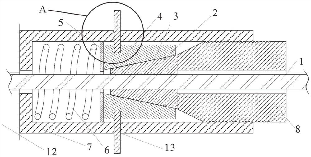
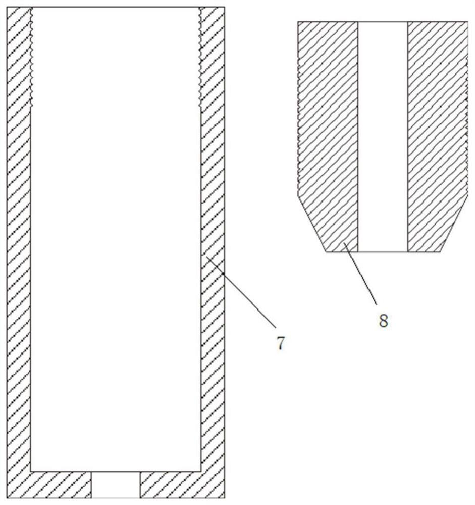
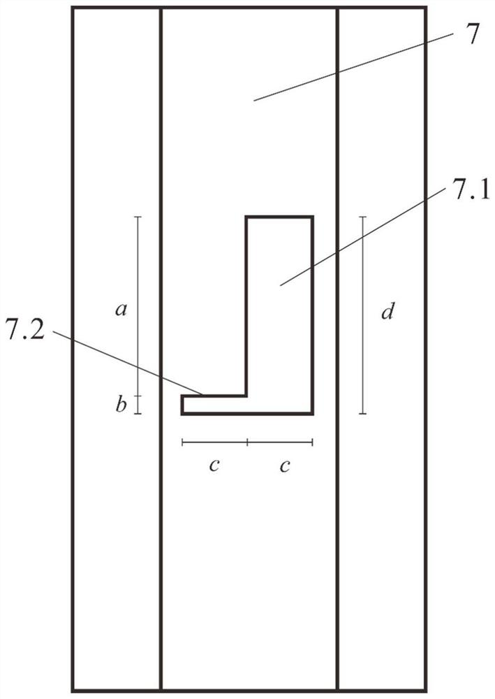
[0039] In embodiment 1: the rigidity K=100.0N / mm of pressing spring 6, then the spring internal force size F s =K·ΔL, ΔL is the compression amount of the spring in the output direction; the inner diameter of the through hole of the outer sleeve 7 is d+10.0mm, the wall thickness is 5.0mm, and the outer wall is made of hexagonal section according to GB / T6170 standard; the outer sleeve 7 two The side is symmetrically opened with an L-shaped slot hole, which can be inserted into the latch 13; the latch 13 can pass through the L-shaped reserved hole on the outer sleeve, and then can be inserted into the prefabricated annular groove on the outer wall of the anchor ring 4, such as image 3 , 4 As shown; the pin is a long strip plate, the length, width and height are e, (b-2) mm and (c-2) mm respectively, and the dimensions of each detail in the figure are: a=35mm, b=5.0mm, c=15.0 mm, d=40.0mm, e=42.0mm, f=7.0mm.

Embodiment 2

[0040] In Example 2: the inner diameter of the through hole of the pressure bearing ring 9 is d+10.0mm, the bottom is a standard hexagonal section, and the inner wall thickness of the thread is 5.0mm; the adjusting nut is produced according to the standard hexagonal nut standard.

Embodiment 3

[0041] In Example 3, the inner diameter of the through hole of the double-stage outer sleeve 11 is d+20.0mm, the wall thickness is 5.0mm, and the outer wall is made of a hexagonal cross-section according to the GB / T6170 standard.

[0042] In addition, between the inner wall of the sleeve and the outer wall of the compression screw, the pressure-bearing washer and the adjusting nut, ordinary threads with a pitch of 1.5mm are used, and the thread length is 40.0mm. The thread pair extrusion resistance, shear strength and thread self-locking performance of the threaded connection satisfy the following relationship:

[0043]

[0044]

[0045]

[0046] In the formula, F u is the axial force; σ t is the allowable extrusion stress of the material; τ t The shear stress required for the material; d s It is the middle diameter of the external thread of the compression screw or the pressure washer; d 1 is the small diameter of the external thread of the compression screw or t...


PUM


Abstract

The invention discloses an anchorage device. A self-locking reinforced anchorage device structure is formed by a conical clamping piece, an anchor ring and an outer sleeve, coaxial through holes are formed in the conical clamping piece, the anchor ring and the outer sleeve, a through hole of the outer sleeve is a stepped through hole, the through hole of the anchor ring is a conical through hole, one end of the anchor ring makes contact with the inner stepped end face of the through hole of the outer sleeve, one end of the conical clamping piece is arranged in the through hole of the anchor ring, an inner rib is mounted in the through holes of the conical clamping piece, the anchor ring and the outer sleeve in a penetrating manner, a compression screw is in threaded connection in the through hole of the outer sleeve, the end of the compression screw is in contact with the end of the conical clamping piece, a self-locking structure is formed by the compression screw and the outer sleeve, and prestress application is completed. Precise control over prestress is achieved through the length of jacking threads, the clamping piece is stressed and tightened, meanwhile, the outer portion of the anchor ring is restrained by a jacking spring and a plug pin together, and then the inner rib can be effectively engaged and anchored by the clamping piece.

Description

technical field [0001] The invention relates to the technical field of civil engineering, in particular to an anchor device. Background technique [0002] At present, the common anchorage that is widely used in various fields is the clip-type anchorage, which generally includes an anchor ring and a clip. With the outer tapered surface, the clip generally consists of two or three and are used together, and the inner surface of the clip is provided with transverse threads, which is convenient for occlusal inner ribs. the anchoring state. When in use, the steel strands or prestressed tendons are fixed in the clip, and the clip is directly worn and fit inside the anchor ring. [0003] For materials such as shape memory alloy rods, aluminum alloy rods, etc., there are basically rod-shaped materials with a smooth surface on the market, and the smooth-round rod-shaped materials are prone to misalignment and slippage during the clamping process with clip-type anchors. . For the ...

Claims


Application Information

Patent Timeline
Patent Type & Authority Applications(China)
IPC IPC(8): E04C5/12E04G21/12
CPCE04C5/12E04C5/125E04G21/12
Inventor 常召群韩萌邢国华刘伯权曹国绒王广森
Owner CHANGAN UNIV
Why Eureka
Try Eureka