Through concrete-filled steel tube tied-arch bridge erection construction method

A technology of steel tube concrete and tied arch bridges, which is applied in bridge construction, erection/assembly of bridges, bridges, etc. It can solve problems such as difficult control of high-altitude construction accuracy, long time occupation of waterways, and influence of river navigation, etc., to achieve structural alignment and construction The effect of easy quality control, small impact and convenient construction

Inactive Publication Date: 2016-06-15
HOHAI UNIV +1
View PDF5 Cites 22 Cited by
  • Summary
  • Abstract
  • Description
  • Claims
  • Application Information

AI Technical Summary

Problems solved by technology

The construction methods of the above two tied arch bridges still have the disadvantages of high-altitude operations (wind bracing, beam and closing section butt joint), many processes, difficult control of high-altitude construction accuracy, and too long time occupied by the waterway, which affects the navigation of the river.

Method used


Image

  • Through concrete-filled steel tube tied-arch bridge erection construction method
  • Through concrete-filled steel tube tied-arch bridge erection construction method
  • Through concrete-filled steel tube tied-arch bridge erection construction method

Examples


Embodiment Construction

[0066] The present invention proposes a new construction method for the erection of a concrete-filled steel tube tie-bar arch bridge. The specific construction process is as follows:

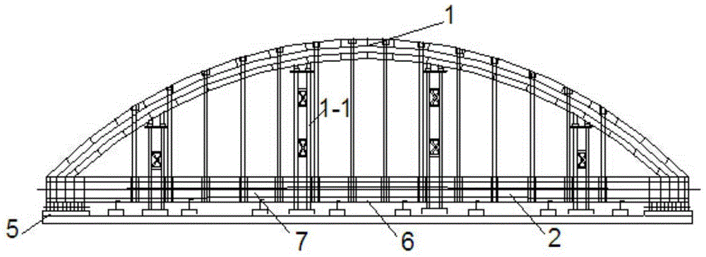
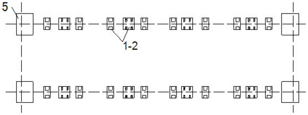
[0067] Step 1: Select a site near the bridge site, and assemble the tire frame on site with high-precision lofting, see Figure 1~Figure 3 ;

[0068] Step 2: Assemble and weld the prefabricated steel pipe arch 1, tie rod stiff frame 2, install wind brace 3 and temporary beam 4, remove temporary fulcrum 5, install tie rod bottom formwork 6 on the stiff frame, bind steel bars, and install inner mold 7, see Figure 1~Figure 3 ;

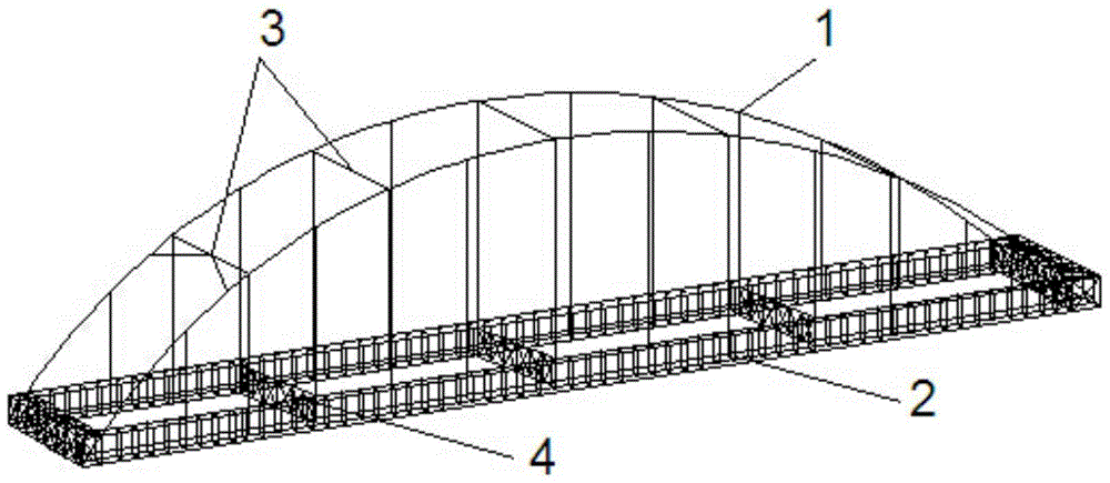
[0069] Step 3: hoist the steel pipe arch and the tie rod rigid framework in place by using the floating crane 8 as a whole, and pull the wind cable 9 at the same time to ensure its stability, see Figure 4 , Figure 5 ;

[0070] Step 4: Concrete pouring of arch foot 10 and end beam 11, all prestressed bundles 12 of tension end beam, see Figure 6 ;

[0071] Step 5: ...


PUM


Abstract

The invention discloses a novel through concrete-filled steel tube tied-arch bridge erection construction method. A through concrete-filled steel tube tied-arch bridge is constructed in the mode that steel tube arches and tie bar stiff frameworks are spliced and welded on site and the bridge is hoisted integrally. The construction method comprises the following steps that site selection is conducted in a position close to the bridge site, and scaffolds are subjected to high-precision setting-out and on-site splicing; steel-pipe arch ribs and the tie bar stiff frameworks are spliced on the scaffolds on site, two arches and tie bars are welded into a whole through wind braces and temporary crossbeams, and a temporary steel tube tied-arch bridge is formed; the temporary steel tube tied-arch bridge which is spliced integrally is hoisted in place through a floating crane; and the tie bars, arch supports and end crossbeam concrete are poured in batches, lifting rods are installed in batches, middle crossbeams are installed in batches, and tie bar prestressing tendons and all the prestressing tendons of the end crossbeams are tensioned. By the adoption of the scheme, a conventional construction method that steel tube arc ribs are hoisted in segments and deck beams are hoisted through temporary cables or supports is replaced, and the construction method has the advantages that construction is convenient, high-altitude work is reduced, structure shapes and construction quality are easy to control, and the influences to the surrounding environment and channel navigation are small.

Description

technical field [0001] The invention relates to a novel construction method for the erection of a concrete-filled steel tube tie-bar arch bridge, which belongs to the technical field of bridge construction. Background technique [0002] In the Jiangnan region, the terrain is flat and soft soil foundations are widely distributed. The under-supported concrete-filled steel tube tied arch bridge, due to its beautiful shape, statically determinate external structure, light structure (suitable for soft soil foundations), and low cost, is widely used in the construction of large and medium-span bridges. be widely used. Especially in recent years, the inland waterways in Jiangsu and Zhejiang have been busy with transportation, and there is an urgent need for inland waterway upgrading and reconstruction projects. This type of bridge has been built in large numbers in the new bridges of the waterway. [0003] The construction methods conventionally adopted for the under-connected con...

Claims


Application Information

Patent Timeline
Patent Type & Authority Applications(China)
IPC IPC(8): E01D21/00
CPCE01D21/00
Inventor 袁爱民王标董华能张怡能竺伟孙大松刘九生张红雷高琦沙扬峰
Owner HOHAI UNIV
Why Eureka
Try Eureka