Thrust roller bearing

A thrust roller bearing and roller technology, applied in the field of bearings, can solve problems such as bearing life impact and limiting bearing use.

Pending Publication Date: 2021-09-10
JIANG SU NAN FANG BEARING CO LTD
View PDF0 Cites 0 Cited by
  • Summary
  • Abstract
  • Description
  • Claims
  • Application Information

AI Technical Summary

Problems solved by technology

[0003] The technical problem to be solved by the present invention is: in order to solve the problem that the thrust roller bearings in the prior art generally

Method used


Image

  • Thrust roller bearing
  • Thrust roller bearing
  • Thrust roller bearing

Examples


Embodiment 1

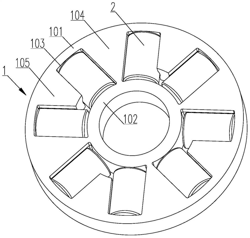
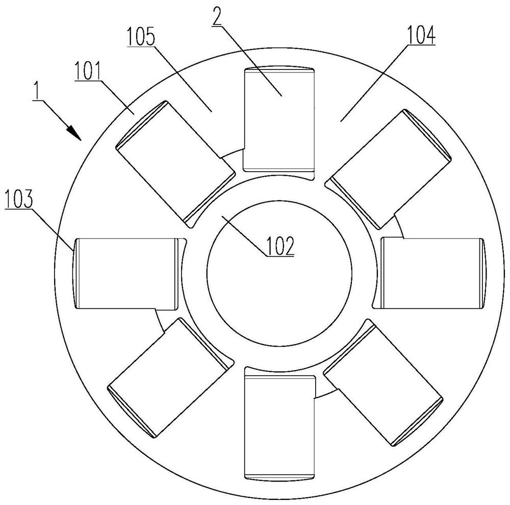
[0033] like Figure 1-5 As shown, a thrust roller bearing includes a cage 1 and several rollers 2;

[0034] The cage 1 includes a ring-shaped outer diameter retaining ring 101 and an inner diameter retaining ring 102, and between the outer diameter retaining ring 101 and the inner diameter retaining ring 102, there are a plurality of outer ends and larger inner ends distributed at different intervals along the circumferential direction. Small connecting beams, windows 103 for accommodating the rollers 2 are formed between two adjacent connecting beams, the windows 103 correspond to the rollers 2 one by one, and the rollers 2 are placed in the corresponding windows 103;

[0035] Among them, there are at least two connecting beams in all connecting beams as the main beam 104, and the remaining connecting beams are sub-beams 105. The outer end of the main beam 104 is fixedly connected to the outer diameter retaining ring 101, and the inner end of the main beam 104 and the inner d...

Embodiment 2

[0046] The difference between embodiment 2 and embodiment 1 is that there are two sub-beams 105 between two adjacent main girders 104, that is, one main girder 104 corresponds to two sub-beams 105, taking nine connecting girders as an example, the main girder There are three beams 104, and six sub-beams 105. In this embodiment, the main beams 104 and the sub-beams 105 are evenly distributed, and the cage 1 is relatively evenly stressed during operation and has a long service life.

Embodiment 3

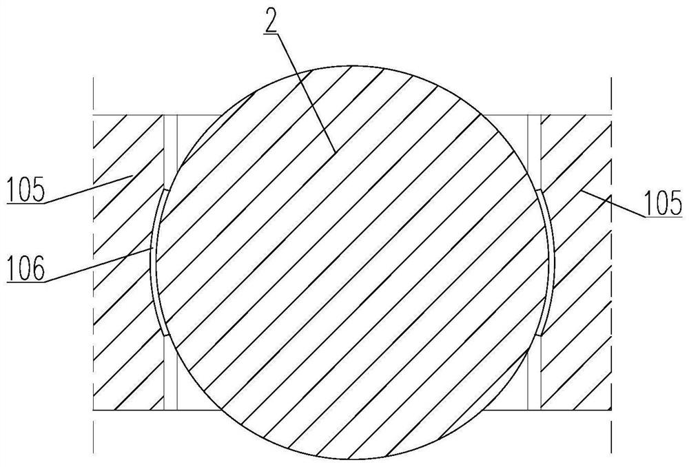
[0048] like Image 6As shown, the difference between Embodiment 3 and Embodiment 1 is that: a part of two adjacent main beams 104 has one sub-beam 105 between them, and another part of adjacent two main girders 104 has two sub-beams 105 between them. That is, there is a situation where one main girder 104 corresponds to one sub-beam 105 and one main girder 104 corresponds to two sub-beams 105. Taking eight connecting beams as an example, there are three main girders 104 and five sub-beams 105. Among the three main beams 104, there are two main beams 104 whose angle A is 48° between the side walls on both sides, and the angle A between the side walls on both sides of the other main beam 104 is 49°. The angle B between the side walls on both sides of the sub-beam 105 is 43°. This embodiment can adapt to the situation that the number of rollers 2 is even, and can ensure the strength of the cage 1 .


PUM


Abstract

The invention relates to the technical field of bearings, in particular to a thrust roller bearing which comprises a retainer and a plurality of rollers, wherein the retainer comprises an annular outer diameter check ring and an annular inner diameter check ring, a plurality of connecting beams with large outer ends and small inner ends are distributed between the outer diameter check ring and the inner diameter check ring in the circumferential direction at unequal intervals, and a window used for containing the rollers is formed between every two adjacent connecting beams; at least two of the connecting beams are main beams, and the other connecting beams are auxiliary beams. The design that the main beams are combined with the auxiliary beams is adopted, the occupied space of the main beams is increased by reducing the occupied space of the auxiliary beams, and the rollers are distributed between the outer diameter check ring and the inner diameter check ring in the circumferential direction in a non-equal-interval mode, so that the number of the rollers is increased in a limited space, the rated load of the bearing is improved, the service life of the bearing is prolonged, the application range of the bearing is widened, meanwhile, the main beams can be connected between the outer diameter check ring and the inner diameter check ring in a large size, and the overall strength of the retainer is guaranteed.

Description

technical field [0001] The invention relates to the technical field of bearings, in particular to a thrust roller bearing. Background technique [0002] Thrust roller bearings have a large market in some bearing application fields due to their high rotation accuracy and large loads, but due to the limited space inside the bearings. In the case of limited installation space, the existing thrust roller bearings generally have a structure with uniformly distributed rollers. However, due to the limitation of the number of rollers in the structure of uniformly distributed rollers during use, the rated load of the bearing is limited and the life of the bearing is greatly affected. It is a great influence, which limits the use of bearings. Contents of the invention [0003] The technical problem to be solved by the present invention is: in order to solve the problem that the thrust roller bearings in the prior art generally have a uniform structure of rollers. , has a great imp...

Claims


Application Information

Patent Timeline
IPC IPC(8): F16C33/52F16C19/32
CPCF16C33/52F16C19/32F16C19/305
Inventor 王雨姜宗成
Owner JIANG SU NAN FANG BEARING CO LTD
Why Eureka
Try Eureka