

Chain guide
A technology for chains and guides, which is applied to chain elements, belts/chains/gears, engine elements, etc., and can solve problems such as the decline in chain lubrication characteristics
- Summary
- Abstract
- Description
- Claims
- Application Information
AI Technical Summary
Problems solved by technology
Method used
Image

Examples
Embodiment 1
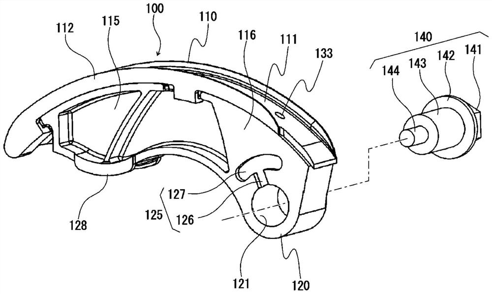
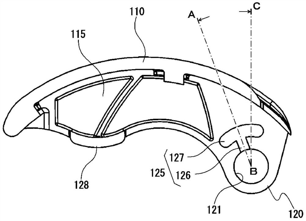
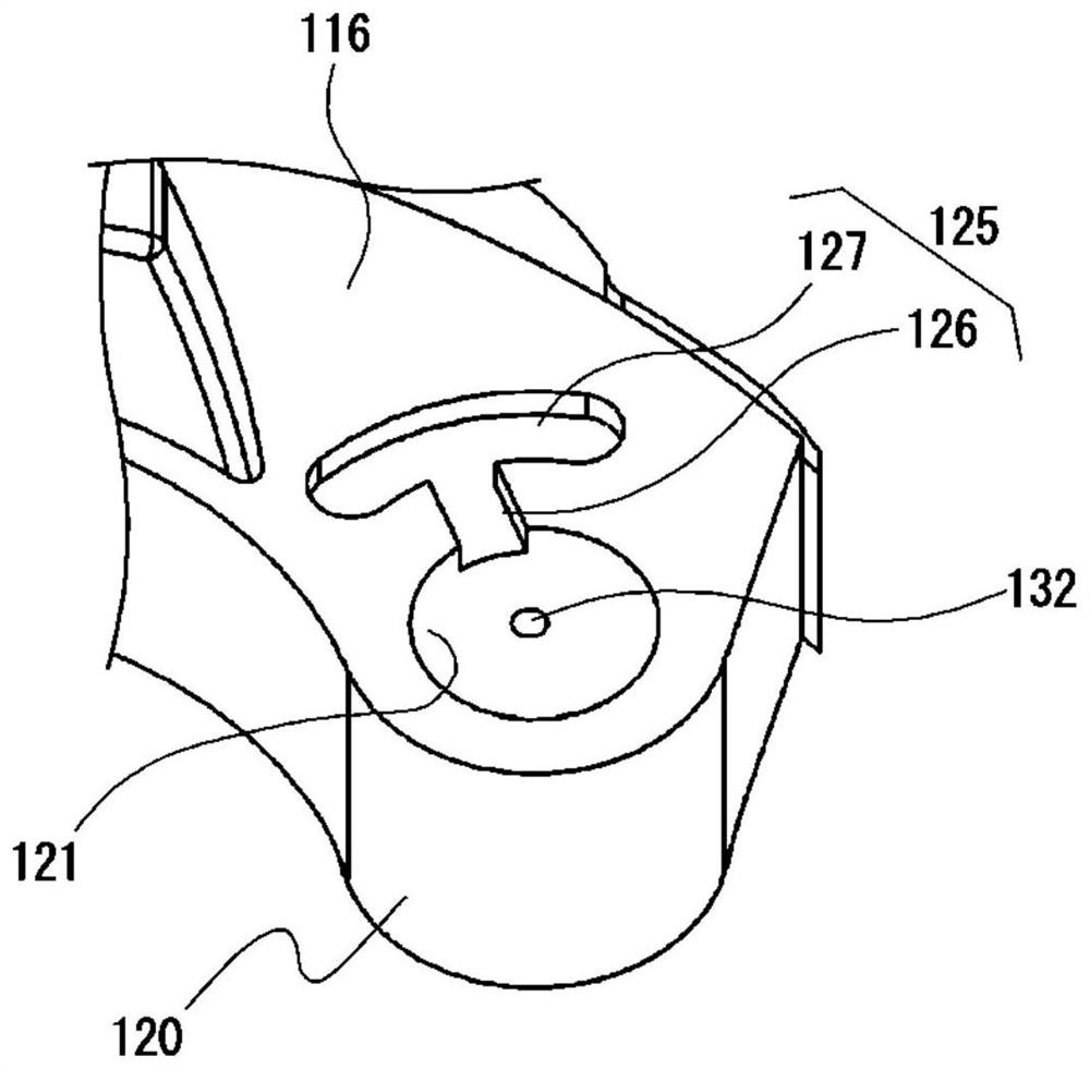
[0047] Such as Figure 1 to Figure 4 As shown, the chain guide 100 according to the first embodiment of the present invention is configured to be swingably mounted to an engine block (not shown) with the mounting screw 140 as a swing shaft, A movable guide that applies appropriate tension to the chain while being linked by a device (not shown).
[0048] The chain guide 100 includes a guide block 110 that slides and guides a moving chain, and a base member 115 that supports the guide block 110 along the longitudinal direction of the guide (chain moving direction). The guide block 110 and the base member 115 are formed of a synthetic resin material or the like.
[0049] The guide block 110 has a chain running surface (sliding surface) 111 extending in the guide length direction, and guide portions 112 protruding upward are vertically provided on both end edges of the chain running surface 111 in the guide width direction.
[0050] The base member 115 is bent along the longitud...
Embodiment 2
[0061] The chain guide according to the second embodiment of the present invention has substantially the same configuration as the chain guide 100 according to the above-mentioned first embodiment except for the configuration of the fuel injection passage. The chain guide according to the present embodiment is configured as a movable guide that is swingably mounted on the engine block by mounting screws, and is coupled with a hydraulic tensioner to apply an appropriate tension to the chain. Such as Figure 6 to Figure 9 As shown, the chain guide 200 includes a guide block 110 that slides and guides a moving chain, and a base member 215 that supports the guide block 110 along the longitudinal direction of the guide (chain moving direction).
[0062] The base member 215 is bent along the longitudinal direction of the guide, has a mounting portion 220 near one end in the longitudinal direction of the guide for mounting to the engine block, and has a hydraulic tensioner near the o...
Embodiment 3
[0067] The chain guide according to the third embodiment of the present invention has substantially the same configuration as the chain guide 100 according to the above-mentioned first embodiment except for the configuration of the fuel injection passage. The chain guide according to the present embodiment is configured as a movable guide which is swingably mounted on the engine block by mounting screws, and is coupled with a hydraulic tensioner to apply an appropriate tension to the chain. Such as Figure 11 and Figure 12 As shown, the chain guide 300 includes a guide block 110 that slides and guides a moving chain, and a base member 315 that supports the guide block 110 along the longitudinal direction of the guide (chain moving direction).
[0068] The base member 315 is formed by bending along the longitudinal direction of the guide, has a mounting portion 320 near one end in the longitudinal direction of the guide for mounting to the engine block, and has a hydraulic te...
PUM
 Abstract
Description
Claims
Application Information