Military equipment overturning test device

A testing device and equipment technology, applied in weapon testing, offensive equipment, weapon accessories, etc., can solve the problems of inability to guarantee the quality, heavy weight, and long test cycle of weapon system products.

Active Publication Date: 2021-09-10
SHENYANG INST OF AUTOMATION - CHINESE ACAD OF SCI
View PDF4 Cites 0 Cited by
  • Summary
  • Abstract
  • Description
  • Claims
  • Application Information

AI Technical Summary

Problems solved by technology

[0002] With the rapid development of science and technology, the technical requirements for the production and testing of military equipment are getting higher and higher. However, in the existing technology, many military equipment have the characteristics of large size and heavy weight. For the artillery vehicle weapon system, the weapon system needs to be hoisted and installed on the self-propelled artillery vehicle first, and then the self-propelled artillery vehicle is hoisted and placed on a fixed platform. Such multiple hoistings make the test cycle longer, which seriously affects the performance test. Work efficiency and accuracy
In addition, a lot of military equipment needs to be tilted for testing, and with the increase of equipment types, its flexibility becomes larger, and the angles that need to be tilted have changed from the original one to a variety of angles. Therefore, only one fixed test platform can no longer meet the test requirements. At present, the above problems are solved by manufacturing multiple fixed platforms with different angles, but this not only requires multiple stations on the production line, occupies a large area, and causes waste of resources and personnel, but also is affected by factors such as platform manufacturing accuracy and platform aging. It will cause loss of accuracy, which will affect the performance test results of the weapon system, so that the product quality of the weapon system cannot be guaranteed

Method used


Image

  • Military equipment overturning test device
  • Military equipment overturning test device
  • Military equipment overturning test device

Examples


Embodiment Construction

[0034] The present invention will be described in further detail below in conjunction with the accompanying drawings.

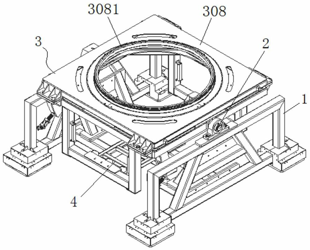
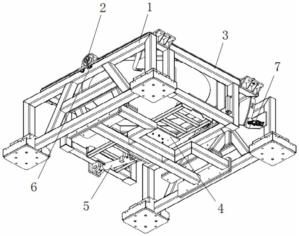
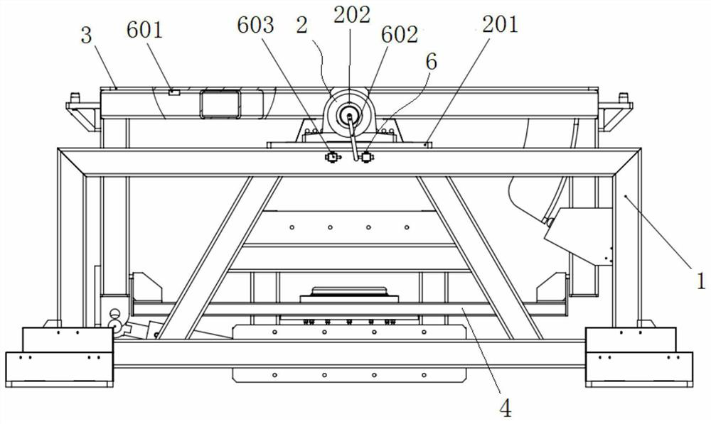
[0035] Such as Figure 1-12 As shown, the present invention includes a test base 1, an overturn frame 3, an overturn driving device 5, a position detection assembly 6 and a locking assembly 7, wherein the test base 1 includes side supports 101 on the left and right sides, and the two sides of the overturn frame 3 The middle part is rotatably mounted on the side brackets 101 on the corresponding sides, the bottom end of the turning drive device 5 is hinged to the bottom of the test base 1, and the upper linear output end is hinged to one end of the turning frame 3, and the turning frame 3 passes through The turning drive device 5 is driven to turn over in the test base 1, and the upper side edge of the turning frame 3 is provided with a support plate 307 with a positioning pin 306, and the positioning pin 306 is used to fix a tray 308 of different types of mil...


PUM


Abstract

The invention relates to the field of military equipment testing, in particular to a military equipment overturning testing device. The military equipment overturning testing device comprises a testing base, an overturning rack, an overturning driving device, a position detection assembly and a locking assembly, wherein, the testing base comprises side supports on the two sides, the middles of the two sides of the overturning rack are rotationally arranged on the side supports on the corresponding sides, the bottom end of the overturning driving device is hinged to the bottom of the testing base, the upper side linear output end of the overturning driving device is hinged to one end of the overturning rack, the upper side edge of the overturning rack is provided with a supporting plate with a positioning pin, the bottom end of the overturning rack is provided with an electric rotation supporting assembly, an angle locking plate with a locking hole is arranged at one end, far away from the overturning driving device, of the overturning rack, the locking assembly is arranged on the test base and provided with a locking shaft matched with the locking hole, and the position detection assembly comprises a tilt angle sensor arranged on the overturning rack. The military equipment overturning testing device is suitable for multi-angle overturning tests of different types of military equipment, the efficiency is improved, the occupied area is saved, and the test precision is guaranteed.

Description

technical field [0001] The invention relates to the field of military equipment testing, in particular to a flip testing device for military equipment. Background technique [0002] With the rapid development of science and technology, the technical requirements for the production and testing of military equipment are getting higher and higher. However, in the existing technology, a lot of military equipment has the characteristics of large size and heavy weight. For the artillery vehicle weapon system, the weapon system needs to be hoisted and installed on the self-propelled artillery vehicle first, and then the self-propelled artillery vehicle is hoisted and placed on a fixed platform. Such multiple hoistings make the test cycle longer and seriously affect the performance test. Work efficiency and accuracy. In addition, a lot of military equipment needs to be tilted for testing, and with the increase of equipment types, its flexibility becomes larger, and the angles that ...

Claims


Application Information

Patent Timeline
Patent Type & Authority Applications(China)
IPC IPC(8): F41A31/00
CPCF41A31/00
Inventor 杜劲松王晓龙刘博常凯华金虎刘江涛杨旭郭锐刘庆君王继万飞
Owner SHENYANG INST OF AUTOMATION - CHINESE ACAD OF SCI
Why Eureka
Try Eureka